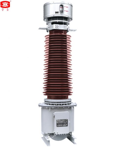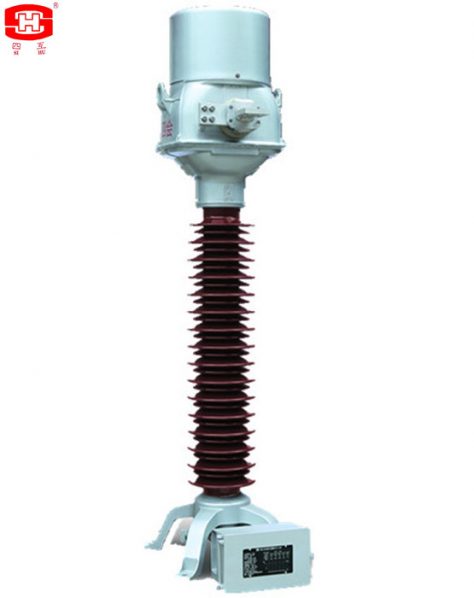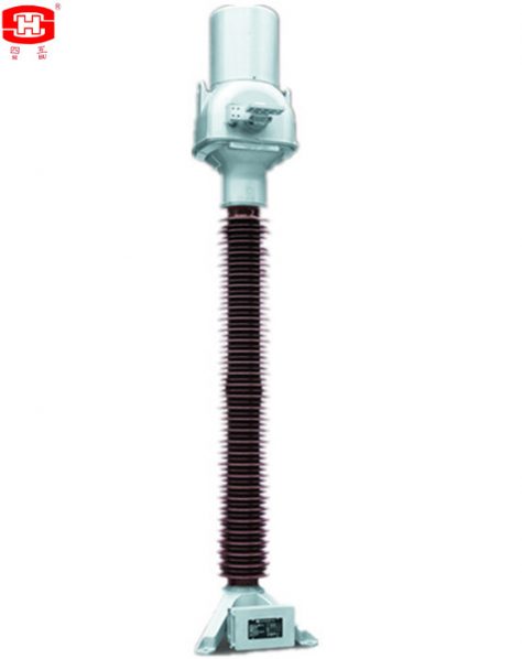


The current transformers which the insulation material is oil. It’s vertical structure, assembled by a metal expander, high voltage porcelain bushing, pressure relief valve, oil tank and oil-letting valve.
The current transformers which the insulation material is oil. It's vertical structure, assembled by a metal expander, high voltage porcelain bushing, pressure relief valve, oil tank and oil-letting valve. The primary winding whose main insulation is made up of crepe paper and capacitor screens. The secondary winding are through the primary winding and are fixed inside the oil tank together. The secondary terminals block is casted by epoxy resin, the frame of the secondary terminals box is a seal structure, it suits for outdoor.
Service Conditions
Ambient air temperature: maximum +40℃, minimum -45℃, average value of the ambient air temperature does not exceed 30℃ measured during a period of 24h.
Altitude: The altitude does not exceed 1000m (this is the routine requirement, if there is any different requirement, we can provide the products with 2000m, 3000m, 4000m or 5000m altitude according to the clients’ requriments).
The average value of the relative humidity does not exceed 95% at 25℃ measured during a period of one month.
The maximum wind speed does not exceed 34m/s.
Eerthquake intensity does not exceed 8 degree.
There have to be no gas that may seriously affect the insulation and conductive ability of electric equipments, steam, ash, salt, chemical deposit, pollution and corrosive or explosive material.
Technical Parameters
Rated frequency is 50Hz or 60Hz
Rated primary current: 10~4000 A
Rated secondary current: 1, 2 or 5 A
Rated output: 10~60VA
Instrument security factor (FS) for metering cores: 5 or 10
Accuracy limit factor: 10, 15, 20, 30, 40, 50 or 60
Accuracy class for metering cores: 0.2, 0.2S, 0.5, 0.5S, 1 or 0.3, 0.6, 1.2
Accuracy class for protection cores: 5P, 10P, PR, PX, TPS, TPX, TPY, TPZ or C10, C20, C50, C100, C200, C400, C800
Rated frequency: 50Hz or 60Hz
Ambient air temperature: -45 ℃/+40 ℃
Altitude: <1000m, if need to design exceed 1000m, please declare in the order.
Rated short-time thermal current: up to 50 kA, 3s; rated dynamic current: up to 125 kA (the actual data shall be corresponding with primary current).
Arcing distance and creepage distance of outer insulation please see table 1.
Table 1
|
Rated voltage (kV) |
Arcing distance (mm) |
Creepage Distance (mm) |
||
|
Pollution Level Ⅱ (W1) |
Pollution Level Ⅲ (W2) |
Pollution Level Ⅳ (W3) |
||
|
35 |
≥410 |
≥810 |
≥1013 |
≥1256 |
|
66 |
≥720 |
≥1450 |
≥1813 |
≥2248 |
|
110 |
≥1010 |
≥2520 |
≥3150 |
≥3906 |
|
132 |
≥1160 |
≥2900 |
≥3625 |
≥4495 |
|
150 |
≥1350 |
≥3400 |
≥4250 |
≥5270 |
|
220 |
≥2010 |
≥5040 |
≥6300 |
≥7812 |
|
330 |
≥2360 |
≥7260 |
≥9075 |
≥11253 |
|
380 |
≥3323 |
≥8400 |
≥10500 |
≥13020 |
|
500 |
≥3980 |
≥11000 |
≥13750 |
≥17050 |
Insulation requirements for the primaries please see table 2.
Table 2
|
Rated voltage (kV) power-frequency withstand voltage (r.m.s) (kV) |
35 95 |
66 |
||
|
160 |
230 |
275 |
||
|
The wet test for the current transformer of power-frequency withstand (r.m.s) (kV) |
95 |
160 |
230 |
275 |
|
Rated switching impulse withstand voltage (peak) (kV) |
— |
— |
— |
— |
|
Rated lightning impulse withstand voltage (peak) (kV) |
200 |
325 |
550 |
650 |
|
chopped ligtning impulse voltage (peak) (kV) |
230 |
373 |
635 |
750 |
|
power-frequency withstand voltage at the SF6 gas pressure 0MPa (kV) |
30 |
54 |
95 |
109 |
|
Partial discharge level |
prestressing performed voltage (r.m.s) (kV) |
76 |
112 |
184 |
|
Test voltage 1.2Um or Um (kV) PD≤10pC |
49 |
87 |
126 |
|
|
Test voltage 1.2Um/√3 (kV) PD≤5pC |
28 |
50 |
87 |
|
|
Rated voltage (kV) |
35 |
66 |
110 |
132 |
Mechanical requirements for the primary terminals please see table 3.
Table 3
|
Rated voltage (kV) Mechanical requirements (horizontal of two directions and vertical) (N) |
35 Load Ⅰ |
66 |
||
|
— |
1250 |
2000 |
||
|
Load Ⅱ |
— |
2500 |
3000 |
|
|
Applied to the primary terminals with duration (s) |
— |
60 |
60 |
60 |
|
Rated voltage (kV) |
35 |
66 |
110 |
132 |
|
Mechanical requirements (horizontal of two directions and vertical) (N) |
Load Ⅰ |
— |
1250 |
2000 |
|
Load Ⅱ |
— |
2500 |
3000 |
|
|
Applied to the primary terminals with duration (s) |
— |
60 |
60 |
60 |
|
Rated voltage (kV) |
35 |
66 |
110 |
132 |
|
Mechanical requirements (horizontal of two directions and vertical) (N) |
Load Ⅰ |
— |
1250 |
2000 |
|
Load Ⅱ |
— |
2500 |
3000 |
|
Dimensions of the Current Transformers
The outline and installation dimensions please see drawing 1~2, and the dimensions of the primary termanils please see table 4~5.

Drawing 1 Drawing 2
1 Oil viewing window 2 Primary terminals 3 Porcelain isolator
4 Earthing Terminal 5 Secondary terminals box 6 Nameplate
Table 4
| Rated Voltage | A (mm) | B (mm) | C (mm) | D (mm) | E (mm) | Drawing No. |
| 35 | 785 | 1463 | 475 | 790 | 20 | 1 |
| 584 | 1770 | 258 | 424 | 14 | 2 | |
| 66 | 785 | 1712 | 475 | 790 | 20 | 1 |
| 630 | 1800 | 410 | 630 | 18 | 2 | |
| 110 | 785 | 2212 | 475 | 790 | 20 | 1 |
| 654 | 2450 | 475 | 710 | 20 | 2 | |
| 132 | 878 | 2375 | 450 | 790 | 20 | 1 |
| 654 | 2750 | 475 | 710 | 20 | 2 | |
| 150 | 878 | 2675 | 450 | 790 | 20 | 1 |
| 654 | 3050 | 475 | 710 | 20 | 2 | |
| 220 | 881 | 3652 | 600 | 760 | 24 | 1 |
| 896 | 375 | 520 | 880 | 24 | 2 |
Notes: There may be any change of the dimensions for the current transformers because of renewing, the clients must basis on the updated drawings.
Search Results for :