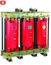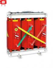
Dry-type Current Transformers with Protective Class
The dry-type current transformer, assemblying by a bushing-type primary winding and secondary winding(s).
Possessing those advantages of light frame, oil-free, gas-free, porcelain-free, fire-proof and explosion-proof etc,
used for current measurement and relay protection in the power system with the rated voltage of 35kV.
a. Ambient air temperature: maximum 40℃, minimum -40℃, average value of the ambient air temperature does not exceed 30℃ measured during a period of 24h.
b. Altitude: The altitude does not exceed 1000m (this is the routine requirement, if there is any different
requirement, we can provide the products with 2000m, 3000m, 4000m or 5000m altitude according to the clients’ requriments).
c. The average value of the relative humidity does not exceed 95% at 25℃ measured during a period of one month.
d. The maximum wind speed does not exceed 34m/s.
e. Eerthquake intensity does not exceed 8 degree.
f. There have to be no gas that may seriously affect the insulation and conductive ability of electric equipments,steam, ash, salt, chemical deposit, pollution and corrosive or explosive material.
Main Technical Parameters
1.1 Rated primary current is 50A~4000A.
1.2 Rated secondary current is 5A or 1A.
1.3 Rated frequency is 50Hz or 60Hz.
1.4 Rated output: 20VA~40VA (If any other rated output required, We can satisfy it.)
1.5 Accuracy classes and their combinations: Steady accuracy classes are 0.2S, 0.2, 0.5S, 0.5, 5P, 10P, PR and PX;
transient accuracy classes are TPS, TPX, TPY and TPZ. There are 1~6 pcs secondary winding(s) in a CT.
1.6 Instrument security factor (FS) of measuring class is 5 or 10.
1.7 Accuracy limit factor (ALF) of protective class is 5, 10, 15, 20, 30 or 40.
1.8 Rated continuous thermal current Icth is 1.2In.
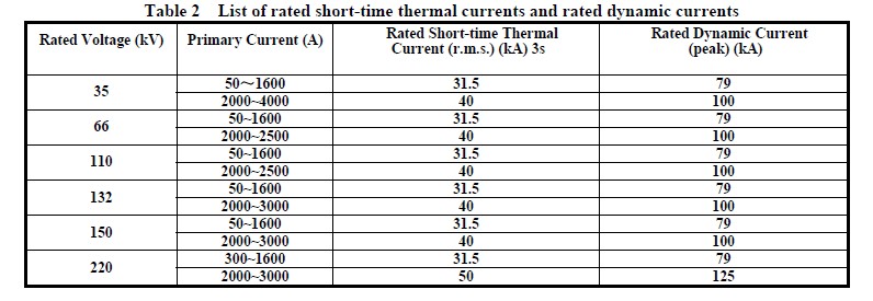
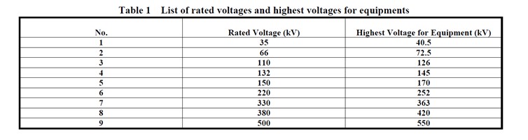
For rated short-time thermal current Ith (r.m.s.) and rated dynamic current Idyn (peak), please see Table 2.
Outline drawing and installation dimensions 

The power transformers are suitable installation for switchgears, and for power plants or substations self-consumption transformers or the places where small space, fire-control, moisture-proof, is needed.
Select of the defend shell: The products can select the beautiful and durable metal shells for more safe. The defend class can select IP20 and IP23 use for indoor. The IP20 shell can prevent the solid things that the diameters are more tham 12mm come into, they are the barriers for the products. IP23 shell can also defend that the drips which are less than 60°with the vertical line come into.
一、Profile of products.
The power transformers are suitable installation for switchgears, and for power plants or substations self-consumption transformers or the places where small space, fire-control, moisture-proof, is needed.
Select of the equipment for forced-air cooling: The cooling method of the product in a general way is natural air cooling, if there is a requirement of the client, we can collocate the system of forced-air cooling for the products of any rated power.
Select of the equipment for temperature display and control: The product can be collocated the equipment for temperature display and control. This equipment can show the temperature of the windings clearly during the product service, and there are many functions such as give an alarm, shut off the power when the trmperature exceed the requirement, turn on and turn off the forced-air cooling, it can be more safe for the product.
Select of the system for microcomputer measure, inspect and control: If the product collocate the microcomputer output connector when it collocate the equipment for temperature display and control, it can select the system for microcomputer measure, inspect and control, to actualize the roboticized manage of power transformer.
二、The functions of this system are as follow:
a) Temperature display and control (give an alarm, shut off the power when the trmperature exceed the requirement, turn on and turn off the forced-air cooling);
b) Electric power measure (can be calaulated the electric power automatically);
c) Inspect the service conditions (current, voltage, temperature, output power, load balance rate, power factor and so on);
d) Deposited the values (can be depositeded 3 years value of the service conditions automatically);
e) Show on line in the microcomputer screen (Show on line of the service conditions);
f) Manage software of the intelligential power transformer ( can be communicated well with person);
g) Printout automatically.
三、Select of the defend shell:
The products can select the beautiful and durable metal shells for more safe. The defend class can select IP20 and IP23 use for indoor. The IP20 shell can prevent the solid things that the diameters are more tham 12mm come into, they are the barriers for the products. IP23 shell can also defend that the drips which are less than 60°with the vertical line come into.
Note: IP23 shell can low down the ability of dissipate heat of the product 5-10%. The structure of the drawing 3 is suit for the indoor product, for the shell of outdoor product must design again.
We can design each kind of shell for the products can be suit for special environment.
四、Technical parameters please see table 1~2
Table 1
|
Voltage Class(kV) |
Rated Short-time Power Frequency Withstand Voltage (r m s) (kV) |
Rated Lightning Impulse Withstand Voltage (peak) (kV) |
|
6 |
20 (or 25) |
60 |
|
10 |
28 (35) |
75 |
|
35 |
70 |
170 |
Table 2
|
Type |
Rated Power (kVA) |
Voltage Combination |
Connection Symbol * |
No-load Loss (W) |
Load Loss (W) (120℃) |
No-load Current (%) |
Impedance (%) |
||
|
HV (kV) |
HV Tapping Range (%) |
LV (kV) |
|||||||
|
SC10-30/10 |
30 |
6 6.3 10 10.5 11 |
±5 or ±2×2.5 |
0.4 |
Yyn0 or Dyn11 |
200 |
710 |
2.6 |
4 |
|
SC10-50/10 |
50 |
280 |
1000 |
2.3 |
|||||
|
SC10-80/10 |
80 |
370 |
1380 |
2.1 |
|||||
|
SC10-100/10 |
100 |
400 |
1580 |
2.0 |
|||||
|
SC10-125/10 |
125 |
480 |
1850 |
1.8 |
|||||
|
SC10-160/10 |
160 |
550 |
2125 |
1.8 |
|||||
|
SC10-200/10 |
200 |
550 |
2530 |
1.1 |
|||||
|
SC10-250/10 |
250 |
630 |
2760 |
1.1 |
|||||
|
SCB10-315/10 |
315 |
770 |
3470 |
0.9 |
|||||
|
SCB10-400/10 |
400 |
850 |
3990 |
0.9 |
|||||
|
SCB10-500/10 |
500 |
1020 |
4880 |
0.9 |
|||||
|
SCB10-630/10 |
630 |
1180 |
5880 |
0.8 |
|||||
|
SCB10-630/10 |
630 |
1130 |
5960 |
0.8 |
6 |
||||
|
SCB10-800/10 |
800 |
1330 |
6960 |
0.8 |
|||||
|
SCB10-1000/10 |
1000 |
1550 |
8130 |
0.8 |
|||||
|
SCB10-1250/10 |
1250 |
1830 |
9690 |
0.8 |
|||||
|
SCB10-1600/10 |
1600 |
2140 |
11730 |
0.8 |
|||||
|
SCB10-2000/10 |
2000 |
2720 |
14450 |
0.6 |
|||||
|
SCB10-2500/10 |
2500 |
3200 |
17170 |
0.6 |
|||||
|
SC10-30/35 |
30 |
35 |
390 |
1150 |
2.5 |
6 |
|||
|
SC10-50/35 |
50 |
450 |
1420 |
2.5 |
|||||
|
SC10-80/35 |
80 |
560 |
1830 |
2.1 |
|||||
|
SC10-100/35 |
100 |
630 |
2090 |
2.1 |
|||||
|
SC10-125/35 |
125 |
700 |
2380 |
1.8 |
|||||
|
SC10-160/35 |
160 |
790 |
2810 |
1.6 |
|||||
|
SC10-200/35 |
200 |
880 |
3320 |
1.6 |
|||||
|
SC10-250/35 |
250 |
990 |
3800 |
1.4 |
|||||
|
SC10-315/35 |
315 |
1170 |
4510 |
1.4 |
|||||
|
SC10-400/35 |
400 |
1370 |
5410 |
1.2 |
|||||
|
SC10-500/35 |
500 |
1620 |
6650 |
1.2 |
|||||
* Clients can appoint a connection symbol different from the above table too, and declare it while ordering.
Note: The highest temperature rise of the products’ windings is 100K, their insulation class is F class, and their cooling mode is AN.
五、Dimensions of the power transformers
For the outline and the installation dimensions please see drawing 1~2 and table 3~4.
Table 3 10kV Power Transformers Installation Dimensions
|
Tpye |
the Installation Dimensions (mm) |
||||||||||
|
H |
H1 |
L |
L1 |
P |
P1 |
E1 |
E2 |
K |
M |
N-D |
|
|
SC10-30/10 |
705 |
— |
749 |
550 |
600 |
550 |
147 |
237 |
259 |
— |
4-Φ14 |
|
SC10-50/10 |
770 |
— |
791 |
550 |
600 |
550 |
153 |
243 |
273 |
— |
4-Φ14 |
|
SC10-80/10 |
815 |
— |
863 |
550 |
600 |
550 |
163 |
253 |
297 |
— |
4-Φ14 |
|
SC10-100/10 |
842 |
— |
892 |
550 |
600 |
550 |
173 |
263 |
306 |
— |
4-Φ14 |
|
SC10-125/10 |
850 |
— |
935 |
550 |
600 |
550 |
176 |
266 |
321 |
— |
4-Φ18 |
|
SC10-160/10 |
930 |
— |
971 |
550 |
600 |
550 |
185 |
270 |
333 |
— |
4-Φ18 |
|
SC10-200/10 |
956 |
— |
998 |
660 |
710 |
660 |
270 |
281 |
342 |
— |
4-Φ18 |
|
SC10-250/10 |
992 |
— |
1067 |
660 |
710 |
660 |
276 |
287 |
365 |
— |
4-Φ18 |
|
SC10-315/10 |
1074 |
— |
1094 |
660 |
710 |
660 |
280 |
291 |
374 |
— |
4-Φ18 |
|
SCB10-400/10 |
1332 |
1327 |
1280 |
660 |
700 |
660 |
270 |
313 |
430 |
138 |
4-Φ13 |
|
SCB10-500/10 |
1367 |
1350 |
1290 |
660 |
700 |
660 |
274 |
320 |
435 |
145 |
4-Φ13 |
|
SCB10-630/10(Uk=4%) |
1537 |
1517 |
1310 |
660 |
820 |
660 |
273 |
323 |
440 |
163 |
8-Φ13 |
|
SCB10-630/10(Uk=6%) |
1342 |
1322 |
1420 |
820 |
980 |
820 |
273 |
323 |
475 |
162 |
8-Φ13 |
|
SCB10-800/10 |
1407 |
1382 |
1480 |
820 |
980 |
820 |
283 |
330 |
495 |
166 |
8-Φ13 |
|
SCB10-1000/10 |
1477 |
1467 |
1550 |
820 |
980 |
820 |
292 |
368 |
520 |
200 |
8-Φ13 |
|
SCB10-1250/10 |
1612 |
1587 |
1590 |
820 |
980 |
820 |
295 |
378 |
535 |
200 |
8-Φ17 |
|
SCB10-1600/10 |
1697 |
1707 |
1690 |
1070 |
1230 |
1070 |
344 |
387 |
570 |
210 |
8-Φ17 |
|
SCB10-2000/10 |
1757 |
1807 |
1850 |
1070 |
1230 |
1070 |
358 |
402 |
615 |
210 |
8-Φ17 |
|
SCB10-2500/10 |
1887 |
1937 |
1910 |
1070 |
1230 |
1070 |
366 |
408 |
640 |
210 |
8-Φ17 |
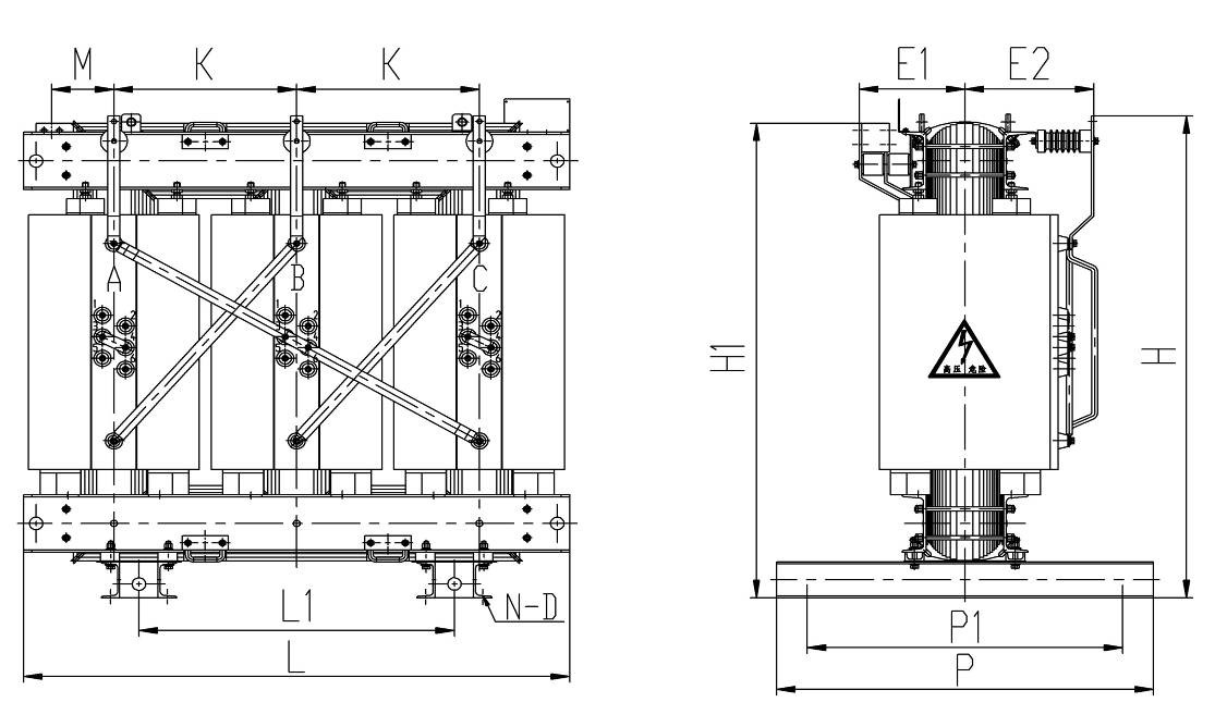
Drawing 1 10kV 30-2500kVA dry-type power transformers outline and installation dimensions
六、Table 4 35kV Power Transformers Installation Dimensions:
|
Tpye |
the Installation Dimensions (mm) |
||||||||||
|
H |
H1 |
L |
L1 |
P |
P1 |
E1 |
E2 |
K |
M |
N-D |
|
|
SC10-30/35 |
1180 |
792 |
1120 |
840 |
280 |
330 |
175 |
475 |
390 |
— |
4-Φ25 |
|
SC10-50/35 |
1120 |
812 |
1120 |
840 |
280 |
330 |
175 |
475 |
390 |
— |
4-Φ25 |
|
SC10-80/35 |
1300 |
860 |
1120 |
840 |
280 |
330 |
175 |
475 |
390 |
— |
4-Φ25 |
|
SC10-100/35 |
1316 |
912 |
1190 |
840 |
310 |
350 |
196 |
418 |
415 |
— |
4-Φ25 |
|
SC10-125/35 |
1382 |
939 |
1190 |
840 |
310 |
350 |
196 |
418 |
415 |
— |
4-Φ25 |
|
SC10-160/35 |
1330 |
895 |
1270 |
660 |
575 |
600 |
210 |
425 |
440 |
— |
4-Φ11 |
|
SC10-200/35 |
1395 |
950 |
1270 |
660 |
575 |
600 |
210 |
425 |
440 |
— |
4-Φ11 |
|
SC10-250/35 |
1425 |
945 |
1365 |
660 |
575 |
600 |
220 |
473 |
475 |
— |
4-Φ11 |
|
SC10-315/35 |
1450 |
945 |
1365 |
660 |
575 |
600 |
220 |
473 |
475 |
— |
4-Φ11 |
|
SC10-400/35 |
1490 |
1005 |
1415 |
820 |
820 |
920 |
295 |
480 |
490 |
— |
8-Φ13 |
|
SC10-500/35 |
1555 |
1015 |
1495 |
820 |
820 |
920 |
305 |
495 |
515 |
— |
8-Φ13 |
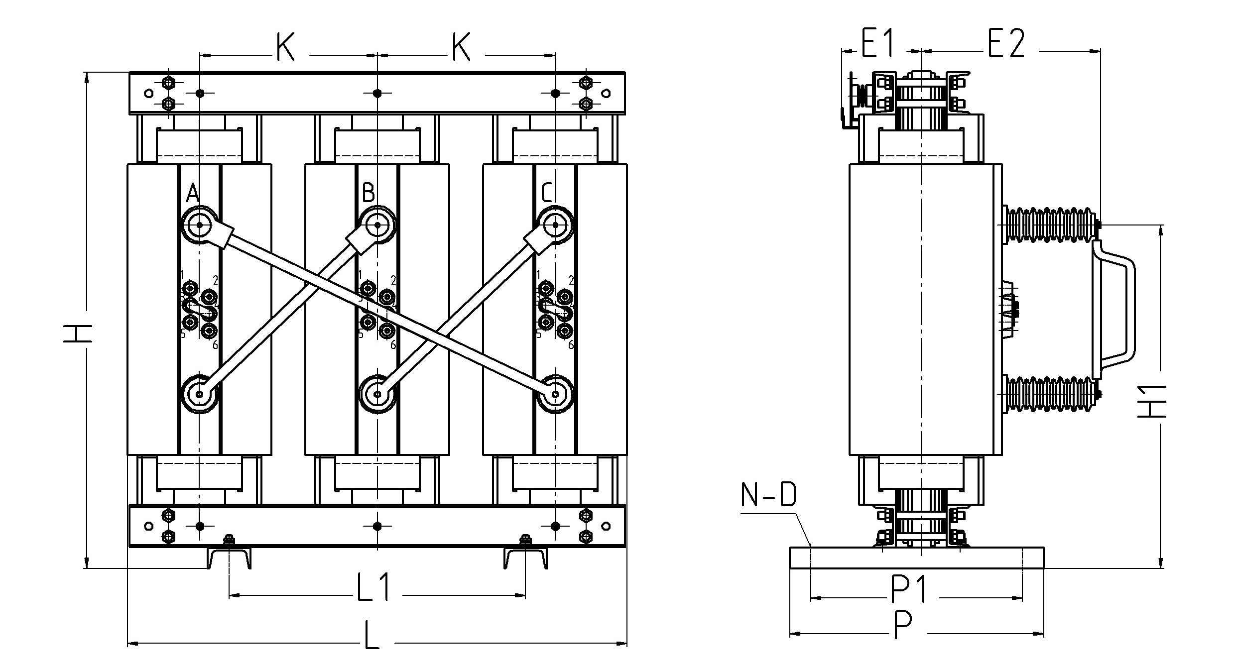 Drawing 2 35kV 30-500kVA dry-type power transformers outline and installation dimensions
Note: The outline and the installation dimensions of table 3 and table 4 are reference for the clients, the actual dimensions are according to the outline of the products.
Epoxy resin insulated voltage inductive voltage transformers, we have without fuse type, fused type, V-connection type, Y-connection type, plateaus type, pole-mounted type and post type and so on. They are widely used in various switchgears of power grid, power plants, substations, railway, and coal mining industries and so on.
Epoxy resin insulated voltage inductive voltage transformers, we have without fuse type, fused type, V-connection type, Y-connection type, plateaus type, pole-mounted type and post type and so on. They are widely used in various switchgears of power grid, power plants, substations, railway, and coal mining industries and so on.
|
Rated Primary Voltage (kV) |
Rated Secondary Voltage (kV) |
Residual Winding Rated Voltage (kV) |
Accuracy Classes |
Rated Outputs (VA) cosΦ=0.8 |
Total Limited Output (VA) |
|
6/√3 6.6/√3 10/√3 11/√3 |
0.1/√3 0.11/√3 0/115/√3 0.12/√3 |
0.1/3 0.11/3 0.115/3 0.12/3 |
0.2/6P | 30/50 | 600 |
| 0.5/6P | 80/50 | ||||
| 1.0/6P | 180/50 | ||||
| 0.2/0.2/6P | 15/15/50 | ||||
| 0.2/0.5/6P | 15/20/50 | ||||
| 0.5/0.5/6P | 40/40/50 |
Note: The data listed in the above table are the normal ones, or we can design them according to the customers’ special requirements.
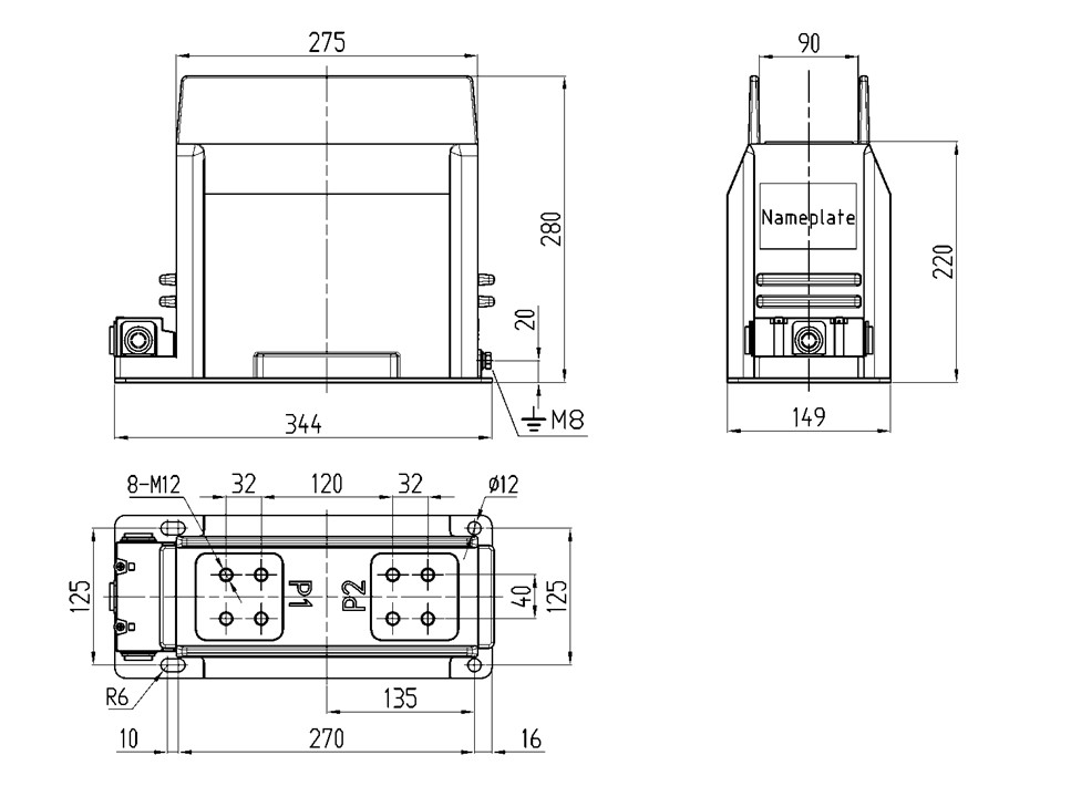
4 Outline drawing and installation dimensions
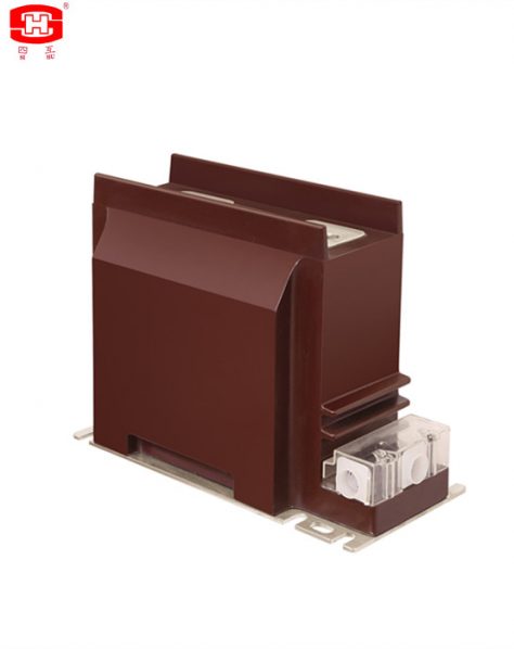
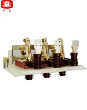
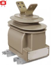
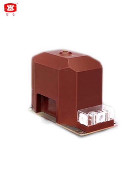
Indoor Type Current Transformers Cast Resin Insulated
LZZBJ9(G)-12/150b/2 indoor current transformer is casting resin insulated, pillar structure, with protective class and fully enclosed. It is used for metering electric energy and current monitoring, relay protection in the electrical system of rated frequency 50/60Hz rated voltage 12/15kV. It can be used for medial voltage AIS, or can be used for medial voltage switchgears. They can operate in all kinds of environments (such as wide range temperature (-50~60℃), high altitude, high humidity, high pollution or salt).
|
Rated Primary Current I1n (A) |
Rated Secondary Current I2n (A) |
Accuracy Classes |
Rated Output (VA) cosΦ=0.8 |
Rated Short-time Thermal Current Ith (kA/s) |
Rated Dynamic Current Idyn (kA) |
Rated Insulation Level (kV) |
|
1500 |
1
5 |
0.2S, 0.2, 0.5S, 0.5 5P10, 5P15, 5P20 10P10, 10P15, 10P20 |
15
20 |
63 |
158 |
12/42/75 |
|
2000 |
Note: The data listed in the above table are the normal ones, we can design them according to the customers’ special requirements. (Standards: GB 20840.2 & IEC 61869-2)
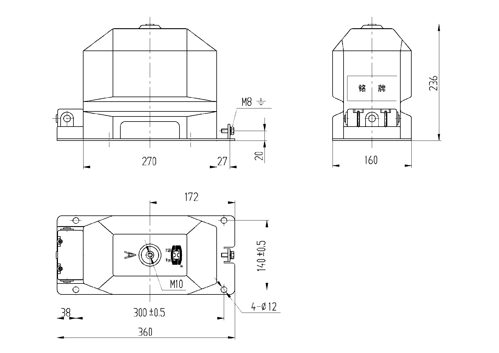
Outline drawing and installation dimensions
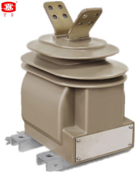
LZZW2(G)-12 outdoor current transformer is casting resin insulated, pillar structure, with protective class and fully enclosed.
LZZW2(G)-12 outdoor current transformer is casting resin insulated, pillar structure, with protective class and fully enclosed. It is used for metering electric energy and current monitoring, relay protection in the electrical system of rated frequency 50/60Hz rated voltage 10 kV. It can be used for medial voltage AIS, or can be used for medial voltage switchgears. They can operate in all kinds of environments (such as wide range temperature (-50~60℃), high altitude, high humidity, high pollution or salt).
|
Rated Primary Current I1n (A) |
Rated Secondary Current I2n (A) |
Accuracy Classes |
Rated Output (VA) cosΦ=0.8 |
Rated Short-time Thermal Current Ith (kA/s) |
Rated Dynamic Current Idyn (kA) |
Rated Insulation Level (kV) |
||
|
0.2S |
0.5 |
5P(10P) |
||||||
|
10~150 |
1
5 |
0.2S, 0.2, 0.5S, 0.5 5P10, 5P15, 5P20 10P10, 10P15, 10P20 |
15 |
15 |
20 |
150 I1n |
2.5 Ith |
12/42/75 |
|
200~250 |
25 |
63 |
||||||
|
300~400 |
15 |
20 |
25 |
31.5 |
80 |
|||
|
500~600 |
40 |
100 |
||||||
Note: The data listed in the above table are the normal ones, or we can design them according to the customers’ special requirements.
Outline drawing and installation dimensions

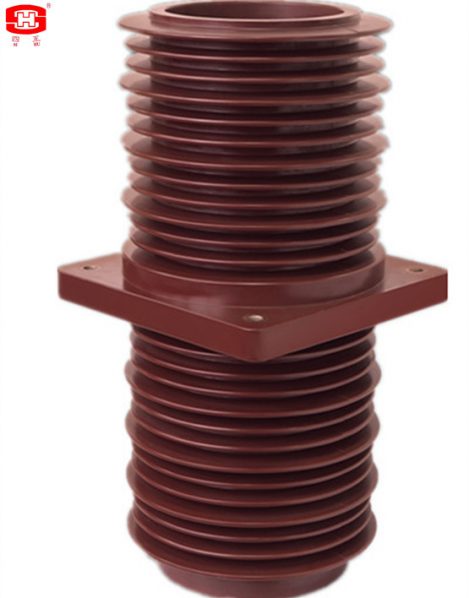
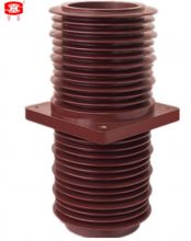
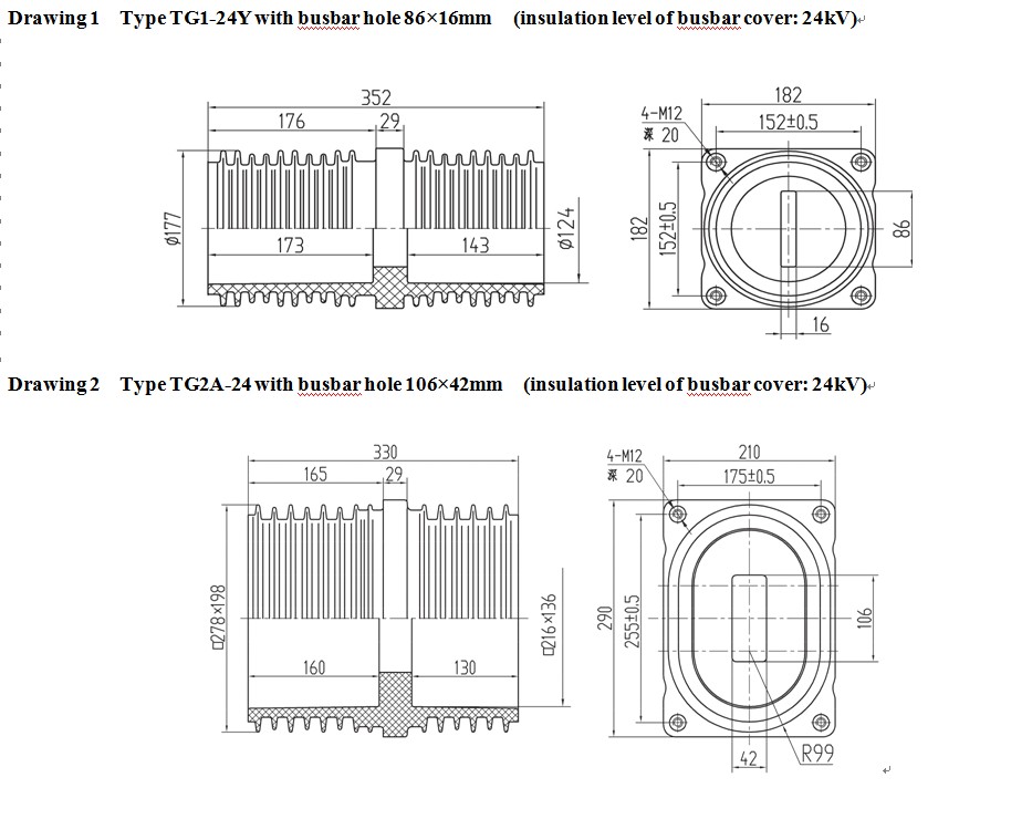
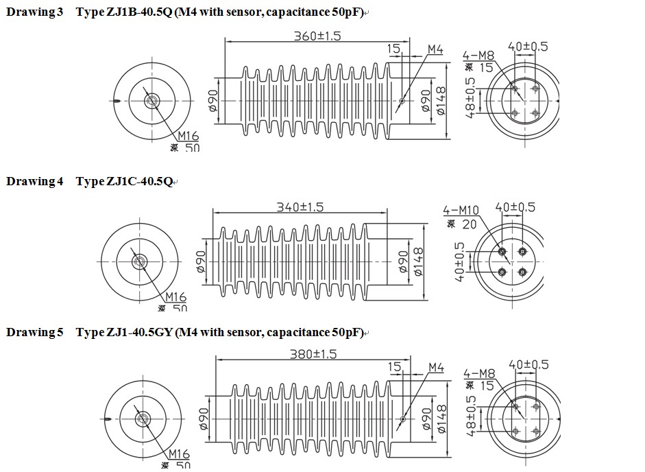
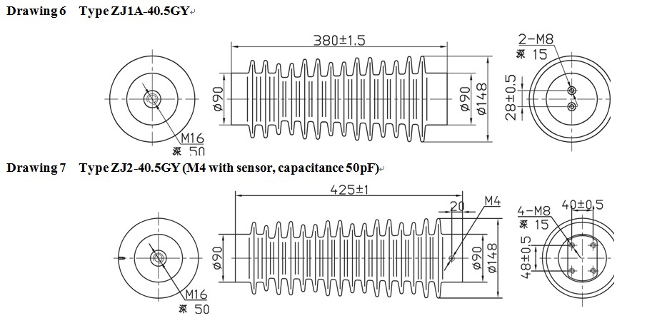
High voltage 40.5kV Epoxy Resin Busbar Bushing Insulator
High voltage 40.5kV Epoxy resin busbar bushing insulator TG-40.5KV
Material: Epoxy Resin
Rated Voltage: 40.5KV
Technology: The Automatic Pressure Gelation (APG)
Application: Used for insulation, isolation & connection transition in various kinds of handcart switchgears.
Service Conditins
1.Attitude:≤1000m
2.Ambient temperature:-10℃~+40℃
3.Relative humidity ≤ 90% at the +20℃ ambient temperature .
4.NO gas,wopor or dust that may severely affect the insulation of contact box, no explosive or corrosive substance.
1. The coper contact to earth shall withstand power frequency test voltage(effective value )of 42kv for 5 minutes and lightning impulse vpltage (peak value)of 75kV.
2. The temperature of lead-out terminal shall not bemore than 65º C if the contact box is used for long time in rated current condition. (Please check below drawings for more infomation).
Outline drawing and dimensions of the insulators
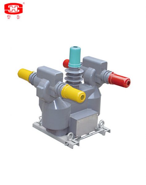
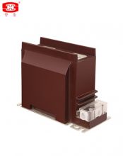
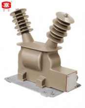
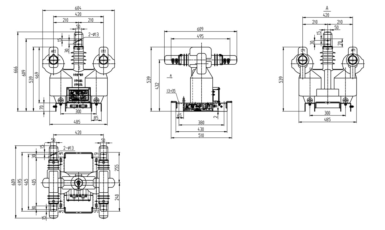
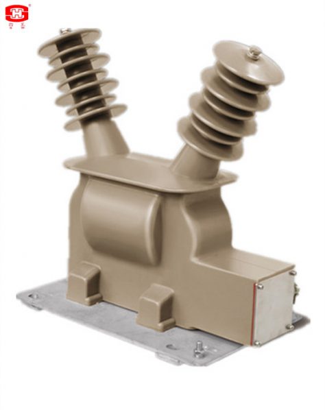
JLSGW1-10A this combined instrument transformer is for use with electrical measuring instruments and electrical protective devices
JLSGW1-10A this combined instrument transformer is for use with electrical measuring instruments and electrical protective devices. It consists of two current transformers and two voltage transformers in the same case.
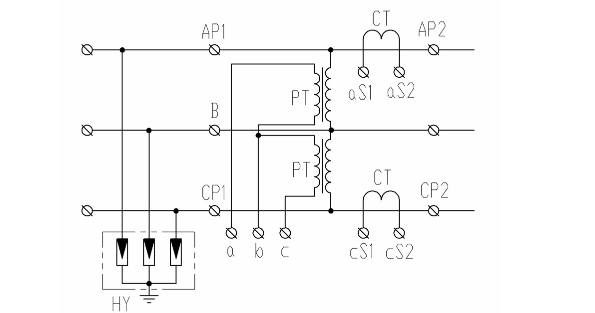
Our combined instrument transformer is especially suitable for HV metering, to do so, two voltage transformers shall be connected in V type, while two current transformers connect serially to phase A and C. The instrument transformer can be fixed on the post of transmitting line. The secondary output connects directly to an independent HV metering box. Users can choose certain connection in accordance with different conditions.
|
Items |
Frequency:50Hz No. of phase:3 |
|
|
VT |
Rated voltage ratio(kV/kV) |
10/0.1 |
|
Connection method for three phase metering |
Two voltage transformers shall be connected in V type |
|
|
Accuracy class |
0.2 |
|
|
Rated secondary output(VA) |
15 |
|
|
Limited output(VA) |
500 |
|
|
Secondary load power factor |
0.8(lag) |
|
|
CT |
Rated current ratio(A/A) |
10~600/5 |
|
Connection method for three phase metering |
2 CTs connected to A,C in primary side in serial. |
|
|
Accuracy class |
0.2S |
|
|
Rated output(VA) |
15 |
|
|
Secondary load power factor |
0.8(lag) |
|
|
Rated short-time thermal current(r.m.s) Ith(kA) |
100I1n |
|
|
Rated dynamic current (Peak) Idyn(kA) |
2.5Ith |
|
Product Feature
This HV measurement set consists of 2 single phase VTs, 2 single phase CTs and 1 surge arresters. The instrument transformers are insulated by outdoor epoxy resin which is suitable for outdoor use. This measurement set is with compact structure, small volume, high accuracy and excellent performance.
In order to meet the requirement of outdoor high voltage metering usage, 2 VTs are in V style connection and 2 CTs are connected serially to phase A and C. There are 2 surge arresters in the power inlet terminal. The voltage loop adopts anti-resonance design, which is rated to increase the primary current by 200% and has strong overload capacity.
Outline drawing and installation dimensions
Electrical Schematic Diagram
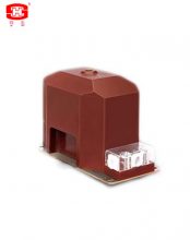
JDZW25(G)-20 is single phase and epoxy resin silicon rubber insulated voltage transformer.
Outdoor voltage transformer of the type JDZW25(G)-20 is single phase and epoxy resin silicon rubber insulated product, it's used for metering electric energy, voltage control and relay protection in 50/60HZ rated voltage 20kV electric system.
It can be used for medial voltage AIS, or can be used for medial voltage switchgears. They can operate in all kinds of environments (such as wide range temperature (-50~60℃), high altitude, high humidity, high pollution or salt).
|
Rated Primary Voltage (kV) |
Rated Secondary Voltage (kV) |
Accuracy Classes |
Rated Outputs (VA) cosΦ=0.8 |
Total Limited Output (VA) |
|
13.8 15 15.75 20 22 |
0.1 0.11 0.115 0.12 0.22 0.23 |
0.2 |
10 |
250 |
|
0.5 |
30 |
|||
|
1.0 |
60 |
|||
|
3.0 |
120 |
Notes:1) The data listed in the above table are the normal ones, or we can design them according to the customers’ special requirements.
2)Standards: GB 20840.3 & IEC 61869-3.
Outline drawing and installation dimensions

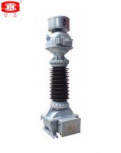
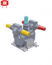
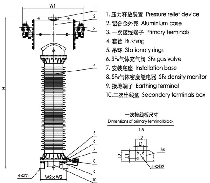
SF6 Gas Insulated Current Transformers.
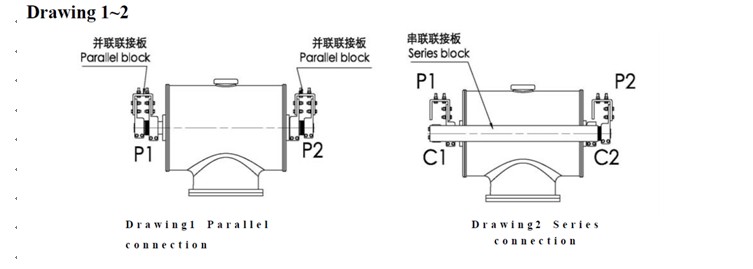
The current transformer is SF6 gas insulation, inverted frame, with the top of T type aluminum case which there are secondary winding(s) and primary winding(s) inside. The bushing is composite materials with silicon rubber umbrellas or high strength porcelain. The secondary terminal leads which through the metal tube are connected with the secondary terminals box which at the base. There is a pressure relief device at the top of the case, when the pressure is more than 0.8MPa (1.0 MPa only for 500 kV) if the current transformer is discharge inside, the relief device will be broken to release the pressure and send an alarm information. There is a SF6 density monitor fix at the base, it can indicate the SF6 pressure which inside the current transformer (its indicated value is the SF6 pressure at 20℃), and it will provide an information when the SF6 pressure is drop down to the minimum service pressure of the current transformer, to remind the user replenish the SF6 gas to the rated pressure.
一、Service Conditions
a. Ambient air temperature: maximum 40℃, minimum -40℃, average value of the ambient air temperature does not exceed 30℃ measured during a period of 24h.
b. Altitude: The altitude does not exceed 1000m (this is the routine requirement, if there is any different requirement, we can provide the products with 2000m, 3000m, 4000m or 5000m altitude according to the clients’ requirements)
c. The average value of the relative humidity does not exceed 95% at 25℃ measured during a period of one month
d. The maximum wind speed does not exceed 34m/s
e. Earthquake intensity does not exceed 8 degree
f. There have to be no gas that may seriously affect the insulation and conductive ability of electric equipments, steam, ash, salt, chemical deposit, pollution and corrosive or explosive material.
二、Main Technical Parameters
4.1 Rated primary current is 50A~4000A
4.2 Rated secondary current is 5A or 1A
4.3 Rated frequency is 50Hz or 60Hz
4.4 Rate output 20VA~50VA (If any other rated output required, We can satisfy it.)
4.5 Accuracy class and t heir combinations: Steady accuracy classes are 0.2S, 0.2, 0.5S, 0.5, 5P, 10P, PR and PX;transient accuracy classes are TPS, TPX, TPY and TPZ. There are 1~6 pcs secondary winding(s) in a CT.
4.6 Rated operating pressure of the SF6 gas is 0.40MPa (0.50 MPa only for 500 kV); Minimum operating pressure of the SF6 gas is 0.35MPa (0.45 MPa only for 500 kV).
4.7 Instrument security factor (FS) of measuring class is 5 or 10.
4.8 Accuracy limit factor (ALF) of protective class is 5, 10, 15, 20, 30 or 40.
4.9 Rated continuous thermal current Icth is 1.2In.
4.10 For rated short-time thermal current Ith (r.m.s.) and rated dynamic current Idyn (peak).
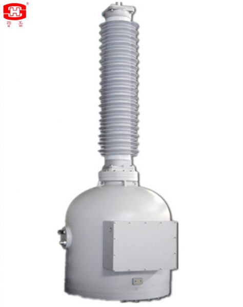
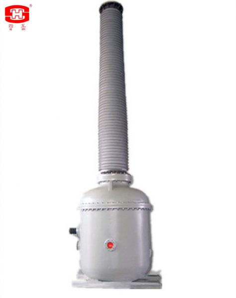
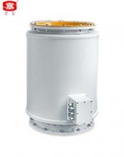
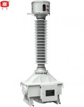
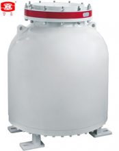
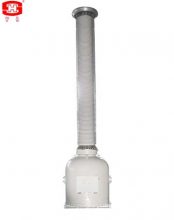
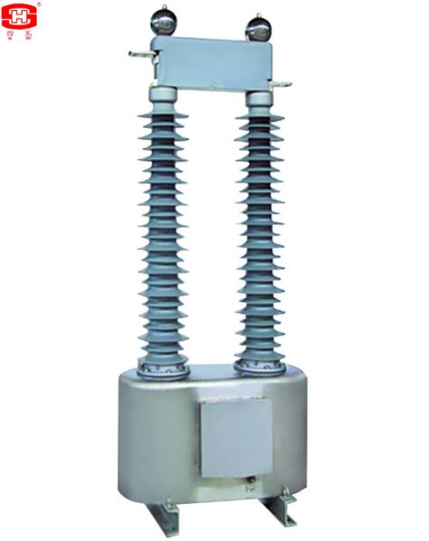
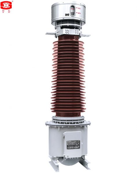
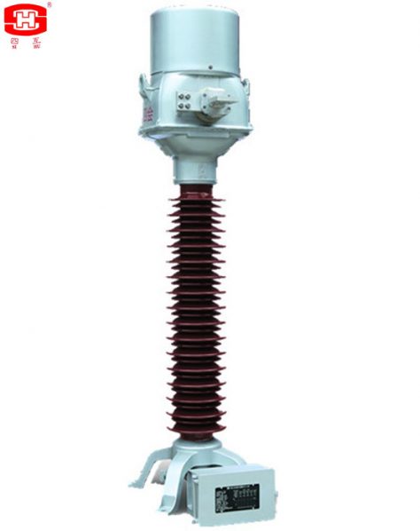
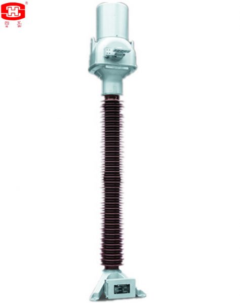
Single-phase Station Service Voltage Transformers gas insulated.
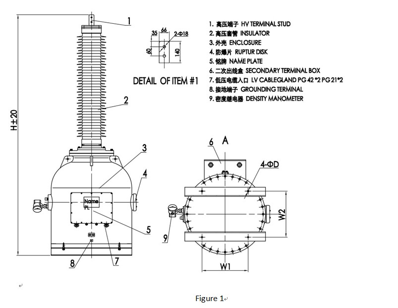
It is a single-phase power transformer which the insulation material is SF6 gas. The bushing of the power transformer is made by silicon rubber or porcelain (for standalone installation). There are some aluminium electrodes inside the power transformer, to improve the electric field distribution inside. There is a pressure relief device at the top of the power transformer, when the pressure is more than 0.8MPa (1.0 MPa only for 500 kV) if the power transformer is discharge inside, the relief device will be broken to release the pressure and send an alarm information. There is a SF6 density monitor fix at the base, it can indicate the SF6 pressure which inside the power transformer (its indicated value is the SF6 pressure at 20℃), and it will provide an information when the SF6 pressure is drop down to the minimum service pressure of the power transformer, to remind the user replenish the SF6 gas to the rated pressure. The secondary terminals block is casted by epoxy resin, the frame of the secondary terminals box is a seal structure, it suits for outdoor. Outline dimensions drawing and structure shown in Figure 1.
一、Service Conditions
a. Ambient air temperature: maximum 40℃, minimum -40℃, average value of the ambient air temperature does not exceed 30℃ measured during a period of 24h.
b. Altitude: The altitude does not exceed 1000m (this is the routine requirement, if there is any different requirement, we can provide the products with 2000m, 3000m, 4000m or 5000m altitude according to the clients’ requirements).
c. The average value of the relative humidity does not exceed 95% at 25℃ measured during a period of one month.
d. The maximum wind speed does not exceed 34m/s.
e. Earthquake intensity does not exceed 8 degree.
f. There have to be no gas that may seriously affect the insulation and conductive ability of electric equipments, steam, ash, salt, chemical deposit, pollution and corrosive or explosive material.
二、Main Technical Parameters.
|
Rated voltage (kV) |
72.5 |
126 |
145 |
170 |
252 |
363 |
420 |
550 |
|
power-frequency withstand voltage (r.m.s) (kV) |
140 |
230 |
275 |
325 |
460 |
510 |
630 |
680 |
|
Rated lightning impulse withstand voltage (peak) (kV) |
325 |
550 |
650 |
750 |
1050 |
1175 |
1425 |
1550 |
|
Rated switching impulse withstand voltage (peak) (kV) |
– |
– |
– |
– |
– |
950 |
1050 |
1175 |
|
Rated output( kVA) |
MAX 333 |
|||||||
|
Secondary voltage |
110~400V,7200~14400V |
|||||||
|
Rated voltage factor |
1.5/30s or others |
|||||||
|
Rate frequency (Hz) |
50/60 |
|||||||
|
Creepage distance( mm/kV) |
25~31 or more high |
|||||||
|
Insulation level |
E/B |
|||||||
|
Accuracy class for metering |
0.2-0.5-1.0* |
|||||||
|
Accuracy class for protection |
3P-6P* |
|||||||
2. Table 2.
|
Table 1Rated voltage (kV) |
Rated output (kVA) |
H (mm) |
W1 (mm) |
W2 (mm) |
D (mm) |
|
72.5 |
25 |
1650 |
400 |
400 |
20 |
|
50 |
1650 |
400 |
400 |
20 |
|
|
75 |
1780 |
600 |
600 |
24 |
|
|
100 |
1922 |
600 |
600 |
24 |
|
|
125 |
1922 |
600 |
600 |
24 |
|
|
126 |
25 |
2005 |
600 |
600 |
24 |
|
50 |
2005 |
600 |
600 |
24 |
|
|
75 |
2272 |
600 |
600 |
24 |
|
|
100 |
2435 |
600 |
600 |
24 |
|
|
125 |
2435 |
600 |
600 |
24 |
|
|
145 |
25 |
2005 |
600 |
600 |
24 |
|
50 |
2005 |
600 |
600 |
24 |
|
|
75 |
2272 |
600 |
600 |
24 |
|
|
100 |
2435 |
600 |
600 |
24 |
|
|
125 |
2435 |
600 |
600 |
24 |
|
|
170 |
25 |
2125 |
600 |
600 |
24 |
|
50 |
2125 |
600 |
600 |
24 |
|
|
75 |
2375 |
600 |
600 |
24 |
|
|
100 |
2568 |
600 |
600 |
24 |
|
|
125 |
2568 |
600 |
600 |
24 |
|
|
252 |
25 |
3670 |
600 |
600 |
24 |
|
50 |
3670 |
600 |
600 |
24 |
|
|
75 |
3822 |
600 |
600 |
24 |
|
|
100 |
3982 |
600 |
600 |
24 |
|
|
125 |
3982 |
600 |
600 |
24 |
|
|
363 |
25 |
4450 |
600 |
600 |
24 |
|
50 |
4522 |
600 |
600 |
24 |
|
|
75 |
4630 |
600 |
600 |
24 |
|
|
100 |
4730 |
600 |
600 |
24 |
|
|
125 |
4730 |
600 |
600 |
24 |
|
|
420 |
25 |
4920 |
600 |
600 |
24 |
|
50 |
4920 |
600 |
600 |
24 |
|
|
75 |
4920 |
680 |
680 |
32 |
|
|
100 |
4920 |
680 |
680 |
32 |
|
|
125 |
4920 |
680 |
680 |
32 |
|
|
550 |
25 |
6220 |
600 |
600 |
24 |
|
50 |
6220 |
600 |
600 |
24 |
|
|
75 |
6438 |
680 |
680 |
32 |
|
|
100 |
6550 |
680 |
680 |
32 |
|
|
125 |
6550 |
680 |
680 |
32 |
|
|
333 |
6550 |
920 |
920 |
32 |
三、Outline dimensions drawing and structure.
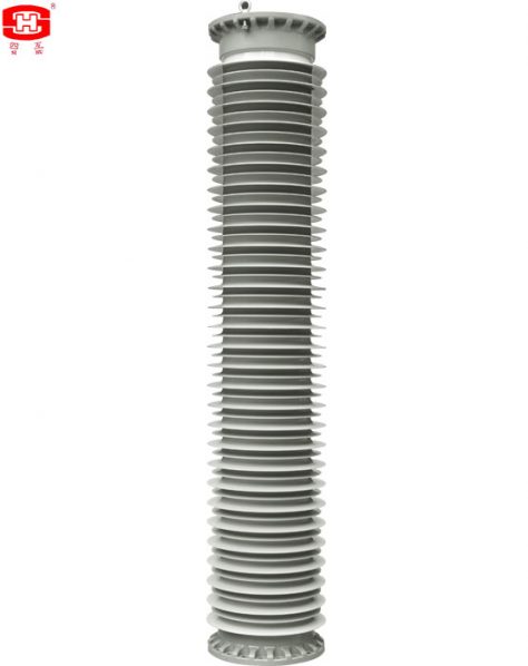
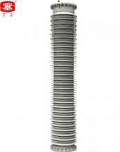
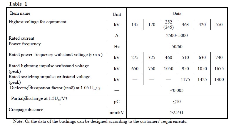
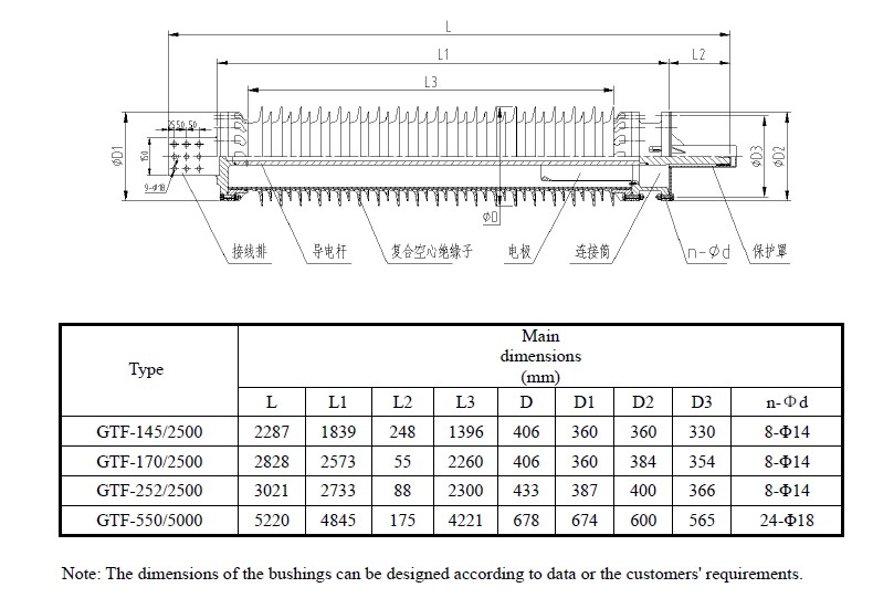
GTF Serial Incoming or Outgoing Bushings for GIS
GTF serial incoming or outgoing bushing for GIS is comprised by terminals, conductor, composite hollow
bushing, shield and transitional flange. terminals and conductor are made by aluminun, the composite hollow
bushing is made by silicon, it has the excellent performances in ageing-resistant, weatherability, hydrofobicity and
pollution-resistance.
Outline drawing and installation dimensions
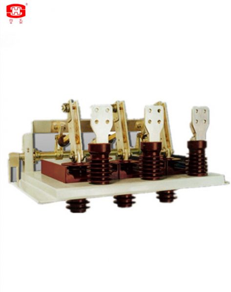
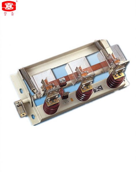
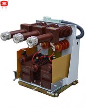
3-Service-Position Indoor HV Isolating Switches
Functions of isolating switch and earthing switch are realized by one driving shaft and one movable contact knife in the condition of air insulation. The product is a new multi-function switch that owns three operation positions of on, isolating (off) and earthing;
The structure of products is reasonable, compact, small volume, safety and reliable. The performance of anti-wrong-operation is quite good. It is an ideal matched product of minimized switchgear;
When switching on and switching off, turn a crank connecting to a shaft by an operating handle, a connection rod makes a movable contact knife rotate for closing, isolating (testing) and earthing.

Dimensions of the voltage transformers


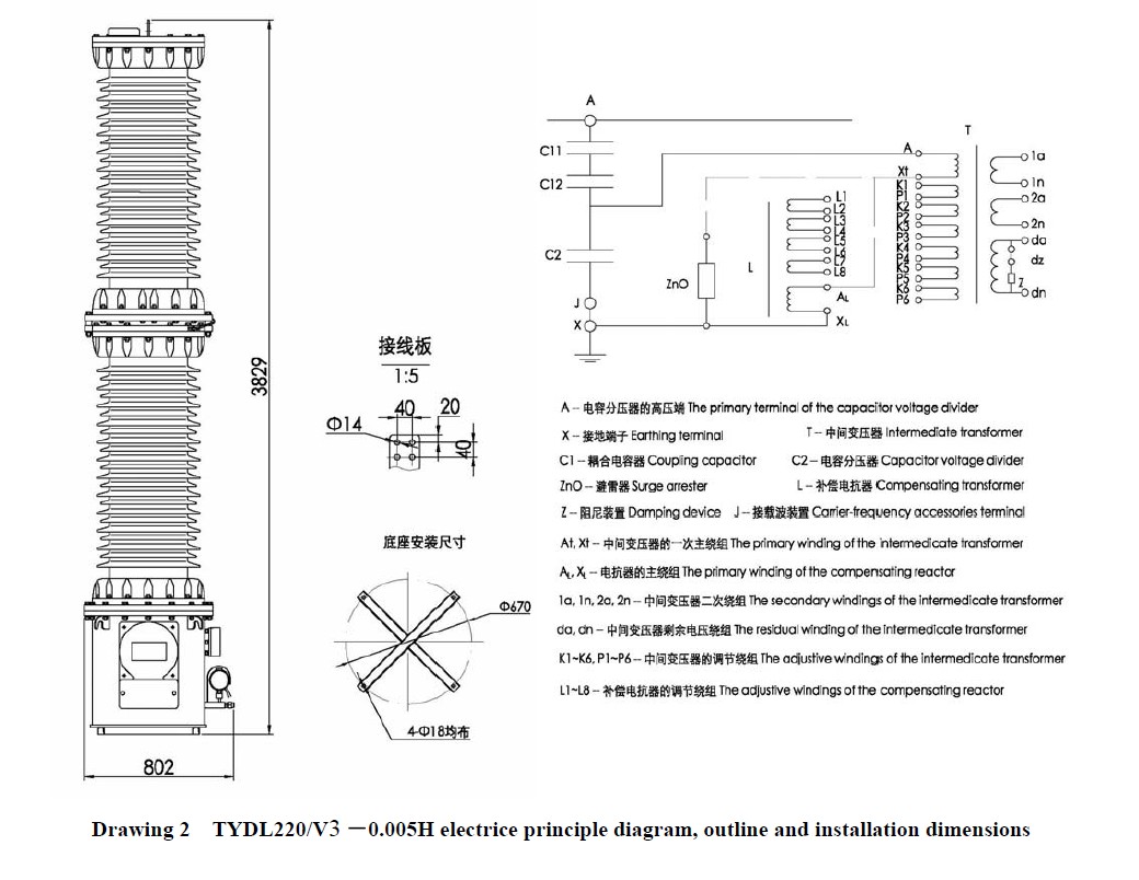
Gas Insulation Capacitive Voltage Transformers with bushing
It is a capacitor voltage transformer which the insulation material is SF6 gas.
The bushing of the capacitor voltage transformer is made by silicon rubber or porcelain. There are some
aluminium electrodes inside the capacitor voltage transformer, to improve the electric field distribution inside
the capacitor voltage transformer.
There is a pressure relief device at the top of the capacitor voltage transformer, when the pressure is more
than 0.8MPa if the capacitor voltage transformer is discharge inside, the relief device will be broken to release
the pressure and send an alarm information.
There is a SF6 density monitor fix at the base, it can indicate the SF6 pressure which inside the capacitor
voltage transformer (its indicated value is the SF6 pressure at 20℃), and it will provide an information when
the SF6 pressure is drop down to the minimum service pressure of the capacitor voltage transformer, to
remind the user replenish the SF6 gas to the rated pressure.
The secondary terminals block is casted by epoxy resin, the frame of the secondary terminals box is a seal
structure, it suits for outdoor.
The nominal capacitance C2N of the capacitor voltage divider which type OM110/ 3 -0.01D for the capacitor
voltage transformer is 0.0211695μF and connected with the primary of electromagnetic unit from the bottom
of the divider.
Electromagnetic unit
The electromagnetic unit is assemblied by an intermediate transformer, compensating reactor, a damping
device and a surge arrester in a case, it is the base of the capacitor voltage divider.
There are two adjustable interstices in the core of the compensating reactor, and there are several adjustive
windings in the compensating reactor’s winding and the primary winding of the intermediate transformer,
theire terminals are connected with the secondary block, to adjust the accuracy freely. The interstices and the
connection of the adjustive windings are fixed before delivery, it shall not allow to change when the capacitor
voltage transformer service.
The low voltage terminal of the capacitor voltage divider is connected with earth firmly before delivery, it shall
not allow to loosen or even open the conncection when the capacitor voltage transformer service.
一、Service Conditions
a. Ambient air temperature: maximum 40℃, minimum -40℃, average value of the ambient air temperature does not exceed 30℃ measured during a period of 24h.
b. Altitude: The altitude does not exceed 1000m (this is the routine requirement, if there is any different requirement, we can provide the products with 2000m, 3000m, 4000m or 5000m altitude according to the clients’ requriments).
c. The average value of the relative humidity does not exceed 95% at 25℃ measured during a period of one month.
d. The maximum wind speed does not exceed 34m/s.
e. Eerthquake intensity does not exceed 8 degree.
f. There have to be no gas that may seriously affect the insulation and conductive ability of electric equipments, steam, ash, salt, chemical deposit, pollution and corrosive or explosive material.
二、Main Technical Parameters
Rated output and relative accuracy class (cosφ=0.8 lag) please see Table 2.
Notes: 1. The quantity of windings, rated output and accuracy listed can be designed according to the requirements of the clients;
2. Eeah thermal limit burden for protective winding is 2000 VA.
3.The system earthing mode is effectively earthed neutral system.


Dimensions of the voltage transformers
Insulating Articles Match High Voltage Switchgears
The single-phase or 3-phase insulators, insulating tubes and insulating rods are match 35~1000kV GIS PASS
or CB high voltage switchgears. Their dimensions, technical parameters and service environments can be
designed according to the requirements of the clients.There are many variants for each kind of the insulator, there are with metal flange or without metal flange,open or close in the epoxy resin, open or close in the insert and so on.
1)Rated voltage: 35kV, 66kV, 110kV, 132kV, 150kV, 220kV, 330kV, 380kV, 500kV, 750kV and 1000kV and so on.
2)Power-frequency withstand voltage performs the standards of GB/T 4109-2008 or IEC 60137:2003.
3)Rated lightning impulse, switching impulse and chopped lightning impulse withstand voltage perform the standards of GB/T 4109-2008 or IEC 60137:2003.
3)Measurement of partial discharge performs the standards of GB/T 4109-2008 or IEC 60137:2003.
4)Mechanical strength: performs the standards of GB/T 4109-2008 or IEC 60137:2003. Or according to the requirements of the clients.
5)Sealed performance: The products must support the rated pressure of SF6, and their gas leak are not exceed 0.1% annually.
Note: These are the routine performance requirements in the above listed, if there is any different required, we can design according to the requirements of the clients.
Main Technical Parameters


Dimensions of the voltage transformers


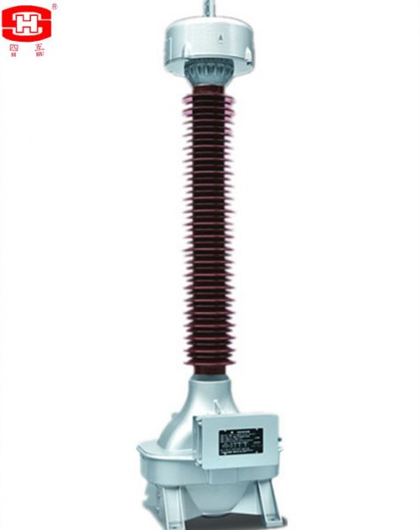
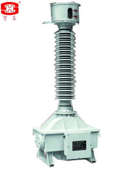
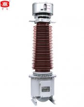
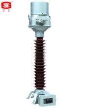
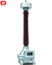
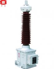
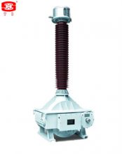
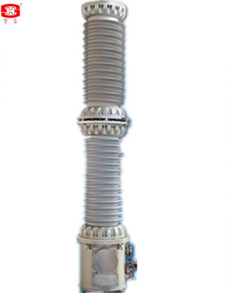
Oil Immersed Inductive Voltage Transformer shall be suitable for measurement control and relay protection in the outdoor AC power system of nominal voltage 40.5~252kV, and frequency of 50 or 60Hz.
Inductive instrument transformer of JDX series shall be suitable for measurement control and relay protection in the outdoor AC power system of nominal voltage 40.5~252kV, and frequency of 50 or 60Hz, this type voltage transformers are oil immersed electromagnetic voltage transformer. The core was used cold-rolled silicon steel strip to folded single-column and three pairs of the same potential with the ground. High voltage coil main insulation chose sheet paper, small oil clearance and large structures. It was wounded as pagoda-shaped segments. High-voltage leads were insulated by a condenser bushing. We select corrugated metal expander as oil temperature variation compensator and can inspect the oil level through window. Fuel tank and the lower tank welded together, and all the other seals are made of sealed limit, effectively preventing the leakage of oil. Outline dimensions drawing and structure shown in Figure 1.
一、Service Conditions
a. Ambient air temperature: maximum +40℃, minimum -45℃, average value of the ambient air temperature does not exceed 30℃ measured during a period of 24h.
b. Altitude: The altitude does not exceed 1000m (this is the routine requirement, if there is any different requirement, we can provide the products with 2000m, 3000m, 4000m or 5000m altitude according to the clients’ requriments).
c. The average value of the relative humidity does not exceed 95% at 25℃ measured during a period of one month.
d. The maximum wind speed does not exceed 34m/s.
e. Eerthquake intensity does not exceed 8 degree.
f. There have to be no gas that may seriously affect the insulation and conductive ability of electric equipments, steam, ash, salt, chemical deposit, pollution and corrosive or explosive material.
二、Main Technical Parameters
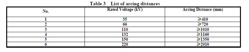
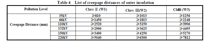
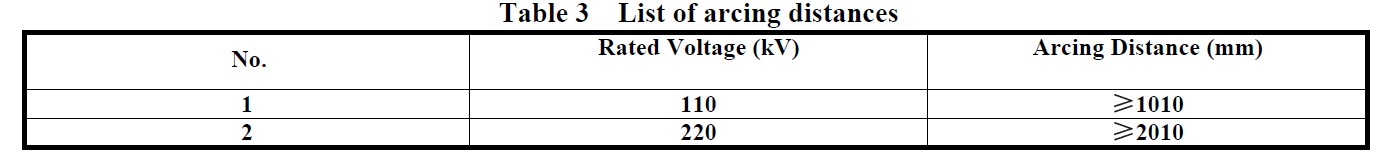
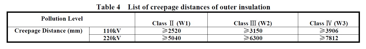
三、Arcing distance and creepage distance of outer insulation please see table 1.
|
Rated voltage (kV) |
Arcing distance (mm) |
Creepage Distance (mm) |
||
|
Pollution Level Ⅱ (W1) |
Pollution Level Ⅲ (W2) |
Pollution Level Ⅳ (W3) |
||
|
35 |
≥410 |
≥810 |
≥1013 |
≥1256 |
|
66 |
≥720 |
≥1450 |
≥1813 |
≥2248 |
|
110 |
≥1010 |
≥2520 |
≥3150 |
≥3906 |
|
132 |
≥1160 |
≥2900 |
≥3625 |
≥4495 |
|
150 |
≥1350 |
≥3400 |
≥4250 |
≥5270 |
|
220 |
≥2010 |
≥5040 |
≥6300 |
≥7812 |
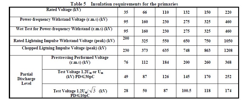
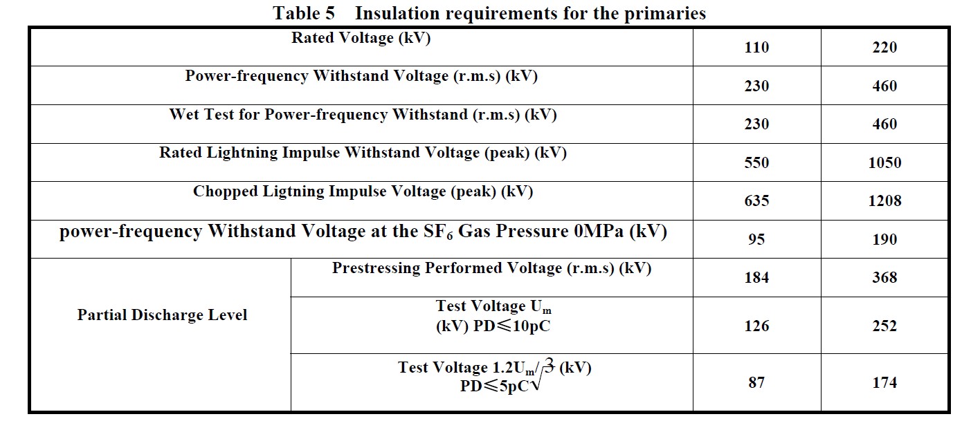
四、Insulation requirements for the primaries please see table 2.
|
Rated voltage (kV) |
35 |
66 |
110 |
132 |
150 |
220 |
|
|
Power-frequency withstand voltage (r.m.s) (kV) |
95 |
140 |
230 |
275 |
325 |
460 |
|
|
The wet test for the current transformer of power-frequency withstand (r.m.s) (kV) |
95 |
140 |
230 |
275 |
325 |
460 |
|
|
Rated lightning impulse withstand voltage (peak) (kV) |
200 |
325 |
550 |
650 |
750 |
1050 |
|
|
Chopped ligtning impulse voltage (peak) (kV) |
230 |
373 |
635 |
750 |
865 |
1208 |
|
|
Partial discharge level |
Prestressing performed voltage (r.m.s) (kV) |
76 |
112 |
184 |
220 |
260 |
368 |
|
Test voltage 1.2Um or Um (kV) PD≤10pC |
49 |
87 |
126 |
145 |
170 |
252 |
|
|
Test voltage 1.2Um/ (kV) PD≤5pC |
28 |
50 |
87 |
100.5 |
118 |
175 |
|
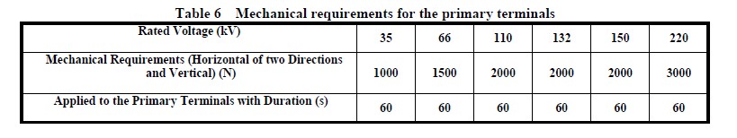
五、Mechanical requirements for the primary terminals please see table 3.
|
Rated voltage (kV) |
35 |
66 |
110 |
132 |
150 |
220 |
|
|
Mechanical requirements (horizontal of two directions and vertical) (N) |
Load |
– |
500 |
1000 |
1000 |
1000 |
1000 |
|
Applied to the primary terminals with duration (s) |
– |
60 |
60 |
60 |
60 |
60 |
|
六、Dimensions Of The Inductive Voltage Transformer
1.The outline and installation dimensions please see drawing 1.
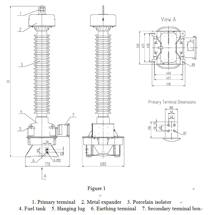
2. The dimensions of the primary termanils please see table 4.
|
Rated Voltage kV |
H1 mm |
H2 mm |
A mm |
B mm |
C mm |
D mm |
|
35 |
1340 |
410 |
550 |
700 |
450 |
20 |
|
66 |
1720 |
720 |
550 |
700 |
450 |
20 |
|
110 |
2090 |
1010 |
670 |
710 |
450 |
20 |
|
132 |
2240 |
1160 |
670 |
710 |
450 |
20 |
|
150 |
2430 |
1350 |
670 |
710 |
450 |
20 |
|
220 |
3860 |
2010 |
680 |
900 |
600 |
24 |
Notes: There may be any change of the dimensions for the inductive voltage transformer because of renewing, the clients must basis on the updated drawings.
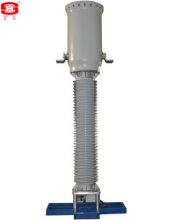
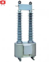
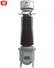
This current transformer has a hermetical structure, each sealing surface has been hermetically sealed by oil resistant rubbers. In order to ensure each of connection fastened well and not to make the gaskets compressed too much, all parts of the equipment are sealed up limitedly.
This current transformer has a hermetical structure, each sealing surface has been hermetically sealed by oil resistant rubbers. In order to ensure each of connection fastened well and not to make the gaskets compressed too much, all parts of the equipment are sealed up limited. The equipment is mainly comprised of metallic bellows, device body, porcelain bushing, oil tank, primary winding terminal plate and secondary winding terminal box. The primary winding forms chain type, using the insulation structure of oilpaper.
Service Conditions
a. Outdoor
b. Ambient air temperature: -45 ~ +40℃(average value of the ambient air temperature does not exceed 30℃ measured during a period of 24h).
c. Altitude ≤1000m(this is the routine requirement, if there is any different requirement, we can provide the products with 2000m, 3000m, 4000m or 5000m altitude according to the clients’ requirements).
d. Application: There have to be no gas that may seriously affect the insulation and conductive ability of electric equipments, steam, ash, salt, chemical deposit, pollution and corrosive or explosive material
e. The average value of the relative humidity does not exceed 95% at 25℃ measured during a period of one month.
f. Max. wind speed ≤34m/s.
g. Earthquake intensity ≤ 7 degree.
Main technical Parameters
Rated frequency:50 or 60Hz
Rated primary current:50 ~ 4000A
Rated secondary current:1 or 5A
Rated output:10~60VA
Instrument security factor(FS) :5 or 10
Accuracy limit factor:10, 15, 20, 30, 40, 50 or 60
Accuracy class for metering cores: 0.2, 0.2S, 0.5, 0.5S, 1 or 0.3, 0.6, 1.2
Accuracy class for protective cores: 5P, 10P, PR, PX, TPS, TPX, TPY, TPZ or C10, C20, C50, C100, C200, C400, C800
Rated short-time thermal current: ≤40kA/3s
Rated dynamic current: ≤100kA
Creepage distance:31mm/kV
Arcing distance and creepage distance of outer insulation please see table 1.
Table 1
|
Rated voltage(kV) |
Arcing distance(mm) |
Creepage Distance (mm) |
|
35 |
≥470 |
≥1256 |
|
66 |
≥720 |
≥2248 |
|
110 |
≥1350 |
≥3906 |
|
132 |
≥1500 |
≥4495 |
|
150 |
≥1710 |
≥5270 |
|
220 |
≥1975 |
≥7812 |
Insulation requirements for the primaries please see table 2.
Table 2
|
Rated voltage (kV) |
35 |
66 |
110 |
132 |
150 |
220 |
|
|
power-frequency withstand voltage (r.m.s) (kV) |
95 |
160 |
230 |
275 |
325 |
460 |
|
|
The wet test for the current transformer of power-frequency withstand (r.m.s) (kV) |
95 |
160 |
230 |
275 |
325 |
460 |
|
|
Rated switching impulse withstand voltage (peak) (kV) |
— |
— |
— |
— |
— |
— |
|
|
Rated lightning impulse withstand voltage (peak) (kV) |
200 |
325 |
550 |
650 |
750 |
1050 |
|
|
chopped lightning impulse voltage (peak) (kV) |
230 |
373 |
635 |
750 |
865 |
1208 |
|
|
power-frequency withstand voltage at the SF6 gas pressure 0MPa (kV) |
30 |
54 |
95 |
109 |
128 |
190 |
|
|
Partial discharge level |
prestressing performed voltage (r.m.s) (kV) |
76 |
112 |
184 |
220 |
260 |
368 |
|
Test voltage 1.2Um or Um (kV) PD≤10pC |
49 |
87 |
126 |
145 |
170 |
252 |
|
|
Test voltage 1.2Um/√3 (kV) PD≤5pC |
28 |
50 |
87 |
100.5 |
118 |
174 |
|
Mechanical requirements for the primary terminals please see table 3.
Table 3
|
Rated voltage (kV) |
35 |
66 |
110 |
132 |
150 |
220 |
|
|
Mechanical requirements (horizontal of two directions and vertical) (N) |
Load Ⅰ |
— |
1250 |
2000 |
2000 |
2000 |
2500 |
|
Load Ⅱ |
— |
2500 |
3000 |
3000 |
3000 |
4000 |
|
|
Applied to the primary terminals with duration (s) |
— |
60 |
60 |
60 |
60 |
60 |
|
Dimensions of the Current Transformers
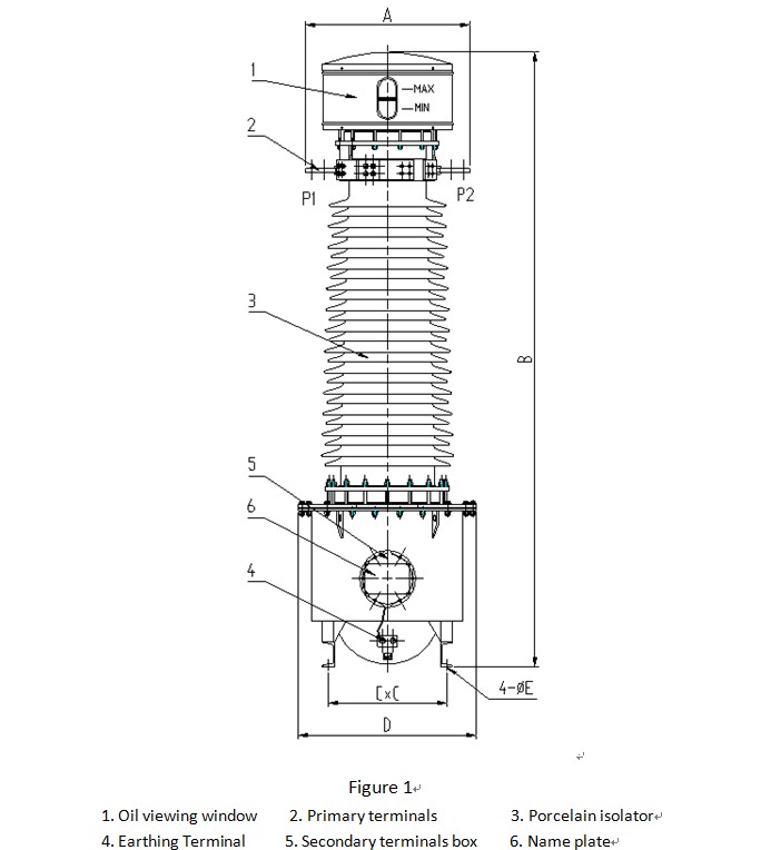
Table 4
|
Rated Voltage |
A (mm) |
B (mm) |
C (mm) |
D (mm) |
E (mm) |
|
35 |
584 |
1770 |
258 |
424 |
14 |
|
66 |
630 |
1800 |
410 |
630 |
18 |
|
110 |
654 |
2450 |
475 |
710 |
20 |
|
132 |
654 |
2750 |
475 |
710 |
20 |
|
150 |
654 |
3050 |
475 |
710 |
20 |
|
220 |
896 |
3715 |
520 |
880 |
24 |
Note:
There may be any change of the dimensions for the current transformers because of renewing, the clients must basis on the updated drawings.
![]()
Search Results for :