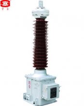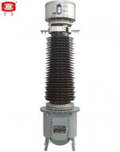


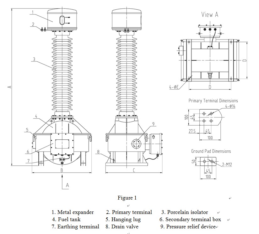
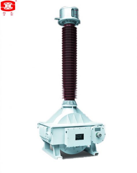
The current transformers which the insulation material is oil. It’s vertical structure, assembled by a metal expander, high voltage porcelain bushing, pressure relief valve, oil tank and oil-letting valve.
The current transformers which the insulation material is oil. It's vertical structure, assembled by a metal expander, high voltage porcelain bushing, pressure relief valve, oil tank and oil-letting valve. The primary winding whose main insulation is made up of crepe paper and capacitor screens. The secondary winding are through the primary winding and are fixed inside the oil tank together. The secondary terminals block is casted by epoxy resin, the frame of the secondary terminals box is a seal structure, it suits for outdoor.
Service Conditions
Ambient air temperature: maximum +40℃, minimum -45℃, average value of the ambient air temperature does not exceed 30℃ measured during a period of 24h.
Altitude: The altitude does not exceed 1000m (this is the routine requirement, if there is any different requirement, we can provide the products with 2000m, 3000m, 4000m or 5000m altitude according to the clients’ requriments).
The average value of the relative humidity does not exceed 95% at 25℃ measured during a period of one month.
The maximum wind speed does not exceed 34m/s.
Eerthquake intensity does not exceed 8 degree.
There have to be no gas that may seriously affect the insulation and conductive ability of electric equipments, steam, ash, salt, chemical deposit, pollution and corrosive or explosive material.
Technical Parameters
Rated frequency is 50Hz or 60Hz
Rated primary current: 10~4000 A
Rated secondary current: 1, 2 or 5 A
Rated output: 10~60VA
Instrument security factor (FS) for metering cores: 5 or 10
Accuracy limit factor: 10, 15, 20, 30, 40, 50 or 60
Accuracy class for metering cores: 0.2, 0.2S, 0.5, 0.5S, 1 or 0.3, 0.6, 1.2
Accuracy class for protection cores: 5P, 10P, PR, PX, TPS, TPX, TPY, TPZ or C10, C20, C50, C100, C200, C400, C800
Rated frequency: 50Hz or 60Hz
Ambient air temperature: -45 ℃/+40 ℃
Altitude: <1000m, if need to design exceed 1000m, please declare in the order.
Rated short-time thermal current: up to 50 kA, 3s; rated dynamic current: up to 125 kA (the actual data shall be corresponding with primary current).
Arcing distance and creepage distance of outer insulation please see table 1.
Table 1
|
Rated voltage (kV) |
Arcing distance (mm) |
Creepage Distance (mm) |
||
|
Pollution Level Ⅱ (W1) |
Pollution Level Ⅲ (W2) |
Pollution Level Ⅳ (W3) |
||
|
35 |
≥410 |
≥810 |
≥1013 |
≥1256 |
|
66 |
≥720 |
≥1450 |
≥1813 |
≥2248 |
|
110 |
≥1010 |
≥2520 |
≥3150 |
≥3906 |
|
132 |
≥1160 |
≥2900 |
≥3625 |
≥4495 |
|
150 |
≥1350 |
≥3400 |
≥4250 |
≥5270 |
|
220 |
≥2010 |
≥5040 |
≥6300 |
≥7812 |
|
330 |
≥2360 |
≥7260 |
≥9075 |
≥11253 |
|
380 |
≥3323 |
≥8400 |
≥10500 |
≥13020 |
|
500 |
≥3980 |
≥11000 |
≥13750 |
≥17050 |
Insulation requirements for the primaries please see table 2.
Table 2
|
Rated voltage (kV) power-frequency withstand voltage (r.m.s) (kV) |
35 95 |
66 |
||
|
160 |
230 |
275 |
||
|
The wet test for the current transformer of power-frequency withstand (r.m.s) (kV) |
95 |
160 |
230 |
275 |
|
Rated switching impulse withstand voltage (peak) (kV) |
— |
— |
— |
— |
|
Rated lightning impulse withstand voltage (peak) (kV) |
200 |
325 |
550 |
650 |
|
chopped ligtning impulse voltage (peak) (kV) |
230 |
373 |
635 |
750 |
|
power-frequency withstand voltage at the SF6 gas pressure 0MPa (kV) |
30 |
54 |
95 |
109 |
|
Partial discharge level |
prestressing performed voltage (r.m.s) (kV) |
76 |
112 |
184 |
|
Test voltage 1.2Um or Um (kV) PD≤10pC |
49 |
87 |
126 |
|
|
Test voltage 1.2Um/√3 (kV) PD≤5pC |
28 |
50 |
87 |
|
|
Rated voltage (kV) |
35 |
66 |
110 |
132 |
Mechanical requirements for the primary terminals please see table 3.
Table 3
|
Rated voltage (kV) Mechanical requirements (horizontal of two directions and vertical) (N) |
35 Load Ⅰ |
66 |
||
|
— |
1250 |
2000 |
||
|
Load Ⅱ |
— |
2500 |
3000 |
|
|
Applied to the primary terminals with duration (s) |
— |
60 |
60 |
60 |
|
Rated voltage (kV) |
35 |
66 |
110 |
132 |
|
Mechanical requirements (horizontal of two directions and vertical) (N) |
Load Ⅰ |
— |
1250 |
2000 |
|
Load Ⅱ |
— |
2500 |
3000 |
|
|
Applied to the primary terminals with duration (s) |
— |
60 |
60 |
60 |
|
Rated voltage (kV) |
35 |
66 |
110 |
132 |
|
Mechanical requirements (horizontal of two directions and vertical) (N) |
Load Ⅰ |
— |
1250 |
2000 |
|
Load Ⅱ |
— |
2500 |
3000 |
|
Dimensions of the Current Transformers
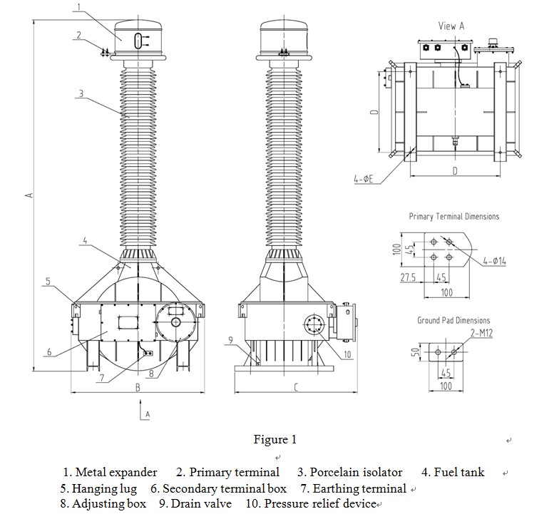
The outline and installation dimensions please see drawing 1~2, and the dimensions of the primary termanils please see table 4~5.

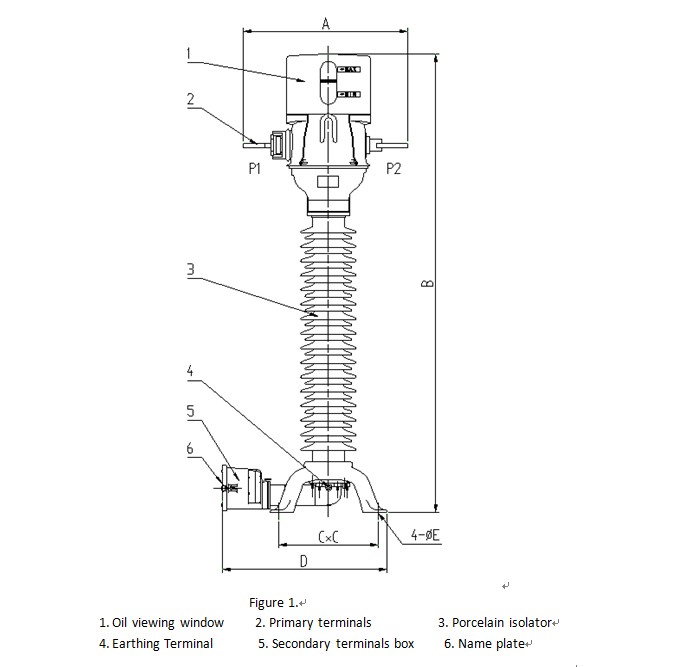
Drawing 1 Drawing 2
1 Oil viewing window 2 Primary terminals 3 Porcelain isolator
4 Earthing Terminal 5 Secondary terminals box 6 Nameplate
Table 4
| Rated Voltage | A (mm) | B (mm) | C (mm) | D (mm) | E (mm) | Drawing No. |
| 35 | 785 | 1463 | 475 | 790 | 20 | 1 |
| 584 | 1770 | 258 | 424 | 14 | 2 | |
| 66 | 785 | 1712 | 475 | 790 | 20 | 1 |
| 630 | 1800 | 410 | 630 | 18 | 2 | |
| 110 | 785 | 2212 | 475 | 790 | 20 | 1 |
| 654 | 2450 | 475 | 710 | 20 | 2 | |
| 132 | 878 | 2375 | 450 | 790 | 20 | 1 |
| 654 | 2750 | 475 | 710 | 20 | 2 | |
| 150 | 878 | 2675 | 450 | 790 | 20 | 1 |
| 654 | 3050 | 475 | 710 | 20 | 2 | |
| 220 | 881 | 3652 | 600 | 760 | 24 | 1 |
| 896 | 375 | 520 | 880 | 24 | 2 |
Notes: There may be any change of the dimensions for the current transformers because of renewing, the clients must basis on the updated drawings.
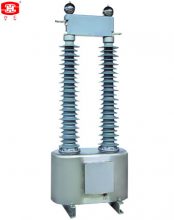
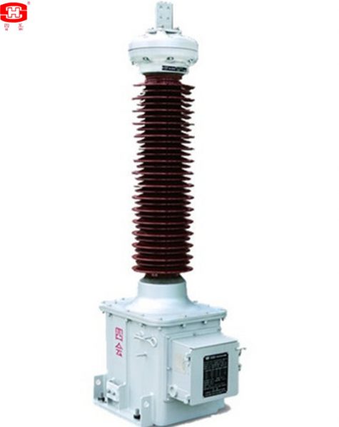
This current transformer is an oil-paper insulated type with a metallic expansion bellow, Connection between components uses argon-arc welding, fill in high pressure nitrogen to detect leakage after assembly is complete.
Current transformer LVB product range is based on top core design. It is an oil-paper insulated type with a metallic expansion bellow, Connection between components uses argon-arc welding, fill in high pressure nitrogen to detect leakage after assembly is complete, so oil penetration and oil leakage caused by oil-immersed products are resolved at root. Use an aluminum alloy cast case, all components including the base, connection box, stainless steel expander, and nameplate etc do not rust forever. It is outdoor, single phase, and oil-immersed to-head type, which is used for metering and relay protection of 220kv, 50 or 60Hz system. It is a reliable product with minimum maintenance and suitable for wide range of environmental conditions.
This product is light and handy with a small volume and light weight and meets the requirement of horizontal transportation.
一、Service Conditions
a. Outdoor
b. Ambient air temperature: –45 ~ +40℃(average value of the ambient air temperature does not exceed 30℃ measured during a period of 24h).
c. Altitude ≤1000m(this is the routine requirement, if there is any different requirement, we can provide the products with 2000m, 3000m, 4000m or 5000m altitude according to the clients’ requirements).
d. Application: There have to be no gas that may seriously affect the insulation and conductive ability of electric equipments, steam, ash, salt, chemical deposit, pollution and corrosive or explosive material
e. The average value of the relative humidity does not exceed 95% at 25℃ measured during a period of one month.
f. Max. wind speed ≤34m/s
g. Earthquake intensity ≤ 7 degree.
二、Technical Parameters
三、Arcing distance and creepage distance of outer insulation please see table 1.
|
Rated voltage(kV) |
Arcing distance(mm) |
Creepage Distance (mm) |
|
35 |
≥410 |
≥1256 |
|
66 |
≥720 |
≥2248 |
|
110 |
≥1010 |
≥3906 |
|
132 |
≥1160 |
≥4495 |
|
150 |
≥1350 |
≥5270 |
|
220 |
≥2010 |
≥7812 |
四、Insulation requirements for the primaries please see table 2.
|
Rated voltage (kV) |
35 |
66 |
110 |
132 |
150 |
220 |
|
|
power-frequency withstand voltage (r.m.s) (kV) |
95 |
160 |
230 |
275 |
325 |
460 |
|
|
The wet test for the current transformer of power-frequency withstand (r.m.s) (kV) |
95 |
160 |
230 |
275 |
325 |
460 |
|
|
Rated switching impulse withstand voltage (peak) (kV) |
— |
— |
— |
— |
— |
— |
|
|
Rated lightning impulse withstand voltage (peak) (kV) |
200 |
325 |
550 |
650 |
750 |
1050 |
|
|
chopped ligtning impulse voltage (peak) (kV) |
230 |
373 |
635 |
750 |
865 |
1208 |
|
|
power-frequency withstand voltage at the SF6 gas pressure 0MPa (kV) |
30 |
54 |
95 |
109 |
128 |
190 |
|
|
Partial discharge level |
prestressing performed voltage (r.m.s) (kV) |
76 |
112 |
184 |
220 |
260 |
368 |
|
Test voltage 1.2Um or Um (kV) PD≤10pC |
49 |
87 |
126 |
145 |
170 |
252 |
|
|
Test voltage 1.2Um/√3 (kV) PD≤5pC |
28 |
50 |
87 |
100.5 |
118 |
174 |
|
五、Mechanical requirements for the primary terminals please see table 3.
|
Rated voltage (kV) |
35 |
66 |
110 |
132 |
150 |
220 |
|
|
Mechanical requirements (horizontal of two directions and vertical) (N) |
Load Ⅰ |
— |
1250 |
2000 |
2000 |
2000 |
2500 |
|
Load Ⅱ |
— |
2500 |
3000 |
3000 |
3000 |
4000 |
|
|
Applied to the primary terminals with duration (s) |
— |
60 |
60 |
60 |
60 |
60 |
|
六、Dimensions and the outline drawing of the Current Transformers.
2. Dimensions of CT
|
Rated Voltage |
A (mm) |
B (mm) |
C (mm) |
D (mm) |
E (mm) |
|
35 |
785 |
1463 |
475 |
790 |
20 |
|
66 |
785 |
1712 |
475 |
790 |
20 |
|
110 |
785 |
2212 |
475 |
790 |
20 |
|
132 |
878 |
2375 |
450 |
790 |
20 |
|
150 |
878 |
2675 |
450 |
790 |
20 |
|
220 |
881 |
3652 |
600 |
760 |
24 |
Note: There may be any change of the dimensions for the current transformers because of renewing, the clients must basis on the updated drawings.
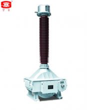
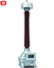
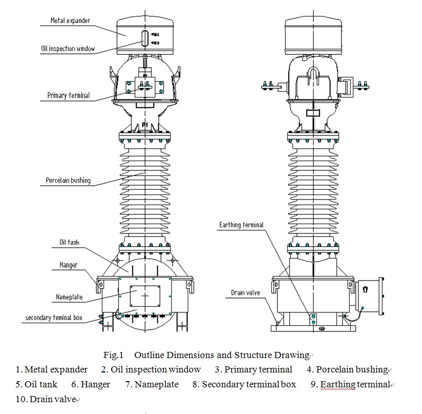
Oil Immersed Inductive Voltage Transformer 110kV, shall be suitable for measurement control and relay protection in the outdoor AC power system of nominal voltage 40.5~252kV, and frequency of 50 or 60Hz.
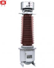
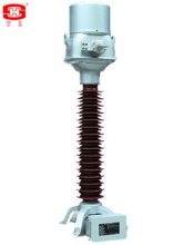
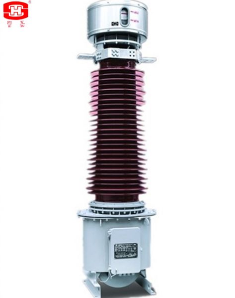
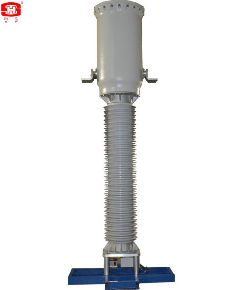
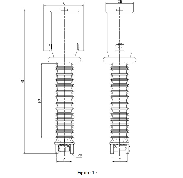
Inductive instrument transformer of JDX series shall be suitable for measurement control and relay protection in the outdoor AC power system of nominal voltage 40.5~252kV, and frequency of 50 or 60Hz, this type voltage transformers are oil immersed electromagnetic voltage transformer. The core was used cold-rolled silicon steel strip to folded single-column and three pairs of the same potential with the ground. High voltage coil main insulation chose sheet paper, small oil clearance and large structures. It was wounded as pagoda-shaped segments. High-voltage leads were insulated by a condenser bushing. We select corrugated metal expander as oil temperature variation compensator and can inspect the oil level through window. Fuel tank and the lower tank welded together, and all the other seals are made of sealed limit, effectively preventing the leakage of oil. Outline dimensions drawing and structure shown in Figure 1
一、Service Conditions
a. Ambient air temperature: maximum +40℃, minimum -45℃, average value of the ambient air temperature does not exceed 30℃ measured during a period of 24h.
b. Altitude: The altitude does not exceed 1000m (this is the routine requirement, if there is any different requirement, we can provide the products with 2000m, 3000m, 4000m or 5000m altitude according to the clients’ requriments).
c. The average value of the relative humidity does not exceed 95% at 25℃ measured during a period of one month.
d. The maximum wind speed does not exceed 34m/s.
e. Eerthquake intensity does not exceed 8 degree.
f. There have to be no gas that may seriously affect the insulation and conductive ability of electric equipments, steam, ash, salt, chemical deposit, pollution and corrosive or explosive material.
二、Main Technical Parameters
三、Arcing distance and creepage distance of outer insulation please see table 1.
|
Rated voltage (kV) |
Arcing distance (mm) |
Creepage Distance (mm) |
||
|
Pollution Level Ⅱ (W1) |
Pollution Level Ⅲ (W2) |
Pollution Level Ⅳ (W3) |
||
|
35 |
≥410 |
≥810 |
≥1013 |
≥1256 |
|
66 |
≥720 |
≥1450 |
≥1813 |
≥2248 |
|
110 |
≥1010 |
≥2520 |
≥3150 |
≥3906 |
|
132 |
≥1160 |
≥2900 |
≥3625 |
≥4495 |
|
150 |
≥1350 |
≥3400 |
≥4250 |
≥5270 |
|
220 |
≥2010 |
≥5040 |
≥6300 |
≥7812 |
四、Insulation requirements for the primaries please see table 2.
|
Rated voltage (kV) |
35 |
66 |
110 |
132 |
150 |
220 |
|
|
Power-frequency withstand voltage (r.m.s) (kV) |
95 |
160 |
230 |
275 |
325 |
460 |
|
|
The wet test for the current transformer of power-frequency withstand (r.m.s) (kV) |
95 |
160 |
230 |
275 |
325 |
460 |
|
|
Rated switching impulse withstand voltage (peak) (kV) |
— |
— |
— |
— |
— |
— |
|
|
Rated lightning impulse withstand voltage (peak) (kV) |
200 |
325 |
550 |
650 |
750 |
1050 |
|
|
Chopped ligtning impulse voltage (peak) (kV) |
230 |
373 |
635 |
750 |
865 |
1208 |
|
|
Partial discharge level |
Prestressing performed voltage (r.m.s) (kV) |
76 |
112 |
184 |
220 |
260 |
368 |
|
Test voltage 1.2Um or Um (kV) PD≤10pC |
49 |
87 |
126 |
145 |
170 |
252 |
|
|
Test voltage 1.2Um/√3 (kV) PD≤5pC |
28 |
50 |
87 |
100.5 |
118 |
174 |
|
五、Mechanical requirements for the primary terminals please see table 3.
|
Rated voltage (kV) |
35 |
66 |
110 |
132 |
150 |
220 |
|
|
Mechanical requirements (horizontal of two directions and vertical) (N) |
Load |
— |
500 |
1000 |
1000 |
1000 |
1250 |
|
Applied to the primary terminals with duration (s) |
— |
60 |
60 |
60 |
60 |
60 |
|
六、Dimensions of Inductive Voltage Transformer
1.The outline and installation dimensions please see drawing 1.
2. The dimensions of the primary termanils please see table 4.
|
Rated Voltage (kV) |
A (mm) |
B (mm) |
C (mm) |
D (mm) |
E (mm) |
|
35 |
1230 |
550 |
650 |
400 |
16 |
|
66 |
1850 |
700 |
670 |
500 |
20 |
|
110 |
2250 |
850 |
810 |
550 |
20 |
|
132 |
2450 |
900 |
860 |
600 |
20 |
|
150 |
2690 |
960 |
900 |
700 |
24 |
|
220 |
3520 |
1050 |
950 |
850 |
24 |
Note: There may be any change of the dimensions for the inductive voltage transformer because of renewing, the clients must basis on the updated drawings.
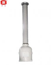
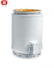
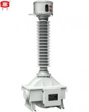
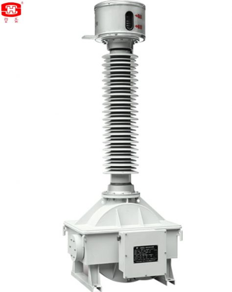
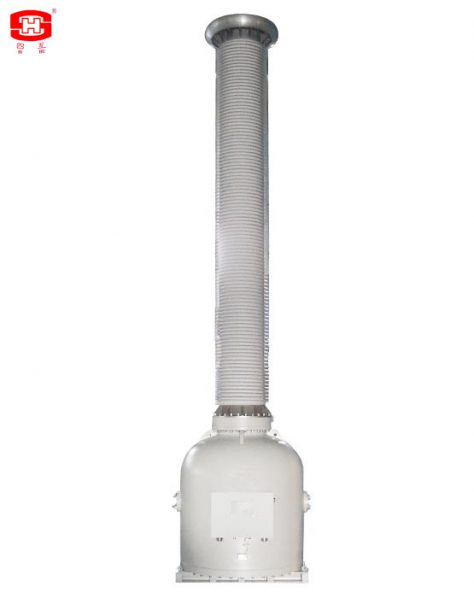
Oil Immersed Station Service Voltage Transformer shall be suitable for measurement control and relay protection in the outdoor AC power system of nominal voltage 40.5~252kV, and frequency of 50 or 60Hz.
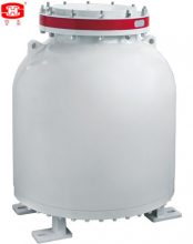
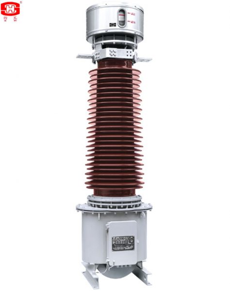
The SSVT (Station service voltage transformer) shall be suitable for measurement control and relay protection in outdoor AC power system of nominal voltage 40.5~252kV, and frequency of 50 or 60Hz. SSVT- type voltage transformers are oil immersed electromagnetic station service voltage transformer. The core was used cold-rolled silicon steel strip to folded single-column and three pairs of the same potential with the ground. High voltage coil main insulation chose sheet paper, small oil clearance and large structures. It was wounded as pagoda-shaped segments. High-voltage leads were insulated by a condenser bushing. We select corrugated metal expander as oil temperature variation compensator and can inspect the oil level through window. Fuel tank and the lower tank welded together, and all the other seals are made of sealed limit, effectively preventing the leakage of oil.
Outline dimensions drawing and structure shown in Figure 1.
一、Service Conditions
a. Ambient air temperature: maximum +40℃, minimum -45℃, average value of the ambient air temperature does not exceed 30℃ measured during a period of 24h.
b. Altitude: The altitude does not exceed 1000m (this is the routine requirement, if there is any different requirement, we can provide the products with 2000m, 3000m, 4000m or 5000m altitude according to the clients’ requriments).
c. The average value of the relative humidity does not exceed 95% at 25℃ measured during a period of one month.
d. The maximum wind speed does not exceed 34m/s.
e. Eerthquake intensity does not exceed 8 degree.
f. There have to be no gas that may seriously affect the insulation and conductive ability of electric equipments, steam, ash, salt, chemical deposit, pollution and corrosive or explosive material.
二、Main Technical Parameters
Note: System earthing conditions: Non-effectively earthed neutral system and effectively earthed neutral system.
三、Arcing distance and creepage distance of outer insulation please see table 1.
|
Rated voltage (kV) |
Arcing distance (mm) |
Creepage Distance (mm) |
||
|
Pollution Level Ⅱ (W1) |
Pollution Level Ⅲ (W2) |
Pollution Level Ⅳ (W3) |
||
|
35 |
≥410 |
≥810 |
≥1013 |
≥1256 |
|
66 |
≥720 |
≥1450 |
≥1813 |
≥2248 |
|
110 |
≥1010 |
≥2520 |
≥3150 |
≥3906 |
|
132 |
≥1160 |
≥2900 |
≥3625 |
≥4495 |
|
150 |
≥1350 |
≥3400 |
≥4250 |
≥5270 |
|
220 |
≥2010 |
≥5040 |
≥6300 |
≥7812 |
四、Insulation requirements for the primaries please see table 2.
|
Rated voltage (kV) |
35 |
66 |
110 |
132 |
150 |
220 |
|
|
power-frequency withstand voltage (r.m.s) (kV) |
95 |
160 |
230 |
275 |
325 |
460 |
|
|
The wet test for the current transformer of power-frequency withstand (r.m.s) (kV) |
95 |
160 |
230 |
275 |
325 |
460 |
|
|
Rated switching impulse withstand voltage (peak) (kV) |
— |
— |
— |
— |
— |
— |
|
|
Rated lightning impulse withstand voltage (peak) (kV) |
200 |
325 |
550 |
650 |
750 |
1050 |
|
|
chopped ligtning impulse voltage (peak) (kV) |
230 |
373 |
635 |
750 |
865 |
1208 |
|
|
Partial discharge level |
prestressing performed voltage (r.m.s) (kV) |
76 |
112 |
184 |
220 |
260 |
368 |
|
Test voltage 1.2Um or Um (kV) PD≤10pC |
49 |
87 |
126 |
145 |
170 |
252 |
|
|
Test voltage 1.2Um/√3 (kV) PD≤5pC |
28 |
50 |
87 |
100.5 |
118 |
174 |
|
五、Mechanical requirements for the primary terminals please see table 3.
|
Rated voltage (kV) |
35 |
66 |
110 |
132 |
150 |
220 |
|
|
Mechanical requirements (horizontal of two directions and vertical) (N) |
Load |
— |
500 |
1000 |
1000 |
1000 |
1250 |
|
Applied to the primary terminals with duration (s) |
— |
60 |
60 |
60 |
60 |
60 |
|
六、Dimensions Of The Station Service Voltage Transformer
|
Rated Voltage (kV) |
Rated output (kVA) |
A (mm) |
B (mm) |
C (mm) |
D (mm) |
E (mm) |
|
35 |
25 |
1490 |
700 |
730 |
600 |
20 |
|
50 |
1650 |
725 |
860 |
630 |
20 |
|
|
75 |
1680 |
755 |
890 |
660 |
20 |
|
|
100 |
1680 |
810 |
890 |
700 |
20 |
|
|
125 |
1700 |
840 |
910 |
740 |
20 |
|
|
66 |
25 |
1890 |
730 |
800 |
650 |
20 |
|
50 |
2020 |
760 |
930 |
680 |
20 |
|
|
75 |
2050 |
790 |
960 |
710 |
20 |
|
|
100 |
2070 |
840 |
980 |
760 |
20 |
|
|
125 |
2110 |
850 |
1020 |
850 |
20 |
|
|
110 |
25 |
2260 |
790 |
900 |
710 |
20 |
|
50 |
2360 |
810 |
980 |
730 |
20 |
|
|
75 |
2390 |
840 |
1010 |
770 |
20 |
|
|
100 |
2410 |
890 |
1030 |
810 |
20 |
|
|
125 |
2460 |
900 |
1070 |
900 |
20 |
|
|
132 |
25 |
2430 |
820 |
930 |
740 |
20 |
|
50 |
2540 |
840 |
1010 |
770 |
20 |
|
|
75 |
2570 |
870 |
1040 |
800 |
20 |
|
|
100 |
2590 |
920 |
1070 |
840 |
20 |
|
|
125 |
2640 |
930 |
1100 |
930 |
20 |
|
|
150 |
25 |
2670 |
850 |
980 |
760 |
24 |
|
50 |
2780 |
870 |
1060 |
790 |
24 |
|
|
75 |
2810 |
900 |
1090 |
820 |
24 |
|
|
100 |
2830 |
950 |
1120 |
860 |
24 |
|
|
125 |
2880 |
960 |
1150 |
950 |
24 |
|
|
220 |
25 |
3610 |
940 |
1100 |
880 |
24 |
|
50 |
3720 |
960 |
1180 |
910 |
24 |
|
|
75 |
3780 |
990 |
1210 |
940 |
24 |
|
|
100 |
3980 |
1340 |
1480 |
1000 |
24 |
|
|
125 |
4050 |
1050 |
1270 |
1070 |
24 |
Note:
There may be any change of the dimensions for the station service voltage transformer because of renewing, the clients must basis on the updated drawings.
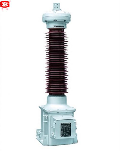
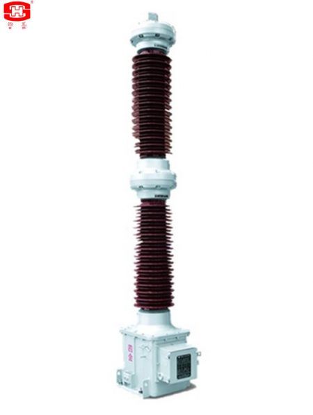
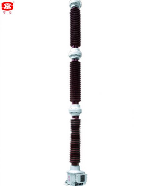
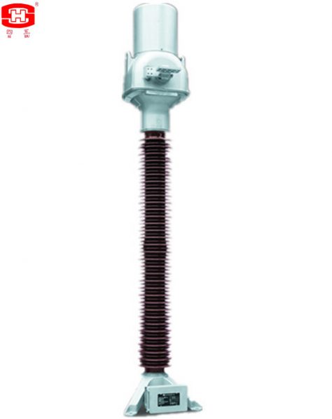
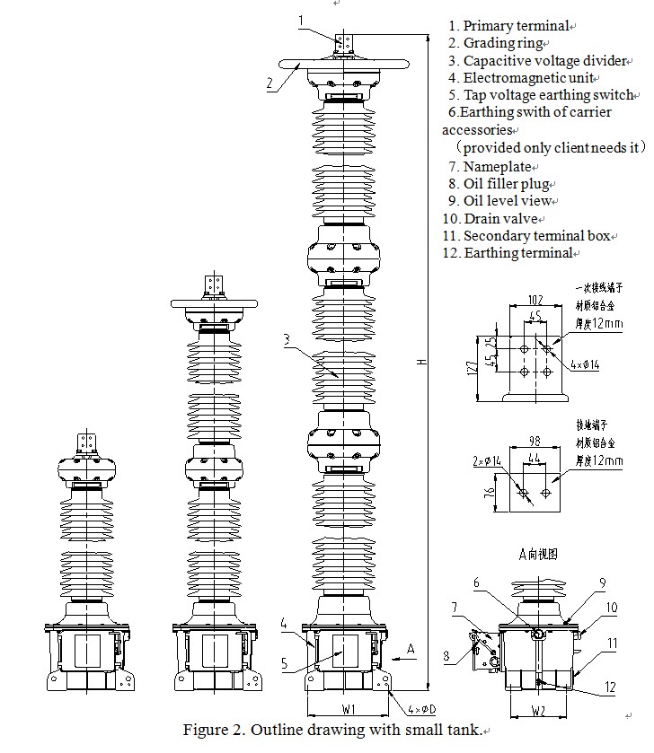
Oil Immersed Capacitor voltage transformer with carrier accessories, also known as coupling capacitor voltage transformer, is abbreviated to CVT.
Capacitor voltage transformer with carrier accessories, also known as coupling capacitor voltage transformer, is abbreviated to CVT. The instrument transformer with carrier accessories shall be suitable for measurement control and relay protection in the outdoor AC power system of nominal voltage 161 kV, BIL750kV, 50Hz and also used for the power line carrier coupling with carrier frequency 50kHz-500 kHz PLC system.
The capacitor voltage divider is mainly composed of porcelain sleeve with flange, bottom sealing plate, capacitor core, upper sealing plate and bellows expander with PXE oil. The electromagnetic unit is mainly composed of cast aluminum case, intermediate transformer, series reactor, anti-resonance device and overvoltage protector, inner part is filled with transformer oil. All parts of the equipment are sealed up limitedly, oil leakage was effectively prevented. The product adopts small design, light weight and novel structure. The product has good insulation performance, can restrain the ferromagnetic resonance phenomenon and run stably. Other devices such as drain rings, spark gap and carrier grounding switches are provided only when the CVT is used as a coupling capacitor for line carrier.
一、Service Conditions
a. Outdoor
b. Ambient air temperature: -45~+40℃(average value of the ambient air temperature does not exceed 30℃ measured during a period of 24h).
c. Altitude ≤1000m(this is the routine requirement, if there is any different requirement, we can provide the products with 2000m, 3000m, 4000m or 5000m altitude according to the clients’ requirements).
d. Application: There have to be no gas that may seriously affect the insulation and conductive ability of electric equipments, steam, ash, salt, chemical deposit, pollution and corrosive or explosive material
e. The average value of the relative humidity does not exceed 95% at 25℃ measured during a period of one month.
f. Max. wind speed ≤34m/s
g. Earthquake intensity ≤7 degree.
二、Main technical Parameters
|
Rated voltage(kV) |
Arcing distance(mm) |
Creepage Distance (mm) |
|
35 |
≥410 |
≥1256 |
|
66 |
≥705 |
≥2248 |
|
110 |
≥1005 |
≥3906 |
|
132 |
≥1160 |
≥4495 |
|
150 |
≥1350 |
≥5270 |
|
220 |
≥2010 |
≥7812 |
|
330 |
≥2700 |
≥11253 |
|
500 |
≥4665 |
≥17050 |
2. Insulation requirements for the primaries please see table 2.
|
Rated voltage (kV) |
35 |
66 |
110 |
132 |
150 |
220 |
330 |
500 |
|
|
Highest Voltage for Equipment (r.m.s.) (kV) |
40.5 |
72.5 |
123 |
145 |
170 |
245 |
363 |
550 |
|
|
power-frequency withstand voltage (r.m.s) (kV) |
95 |
160 |
230 |
275 |
325 |
460 |
510 |
740 |
|
|
The wet test for the current transformer of power-frequency withstand (r.m.s) (kV) |
95 |
160 |
230 |
275 |
325 |
460 |
510 |
740 |
|
|
Rated switching impulse withstand voltage (peak) (kV) |
— |
— |
— |
— |
— |
— |
950 |
1300 |
|
|
Rated lightning impulse withstand voltage (peak) (kV) |
200 |
325 |
550 |
650 |
750 |
1050 |
1175 |
1675 |
|
|
chopped ligtning impulse voltage (peak) (kV) |
230 |
373 |
635 |
750 |
865 |
1208 |
1350 |
1925 |
|
|
Partial discharge level |
prestressing performed voltage (r.m.s) (kV) |
76 |
112 |
184 |
220 |
260 |
368 |
408 |
592 |
|
Test voltage 1.2Um or Um (kV) PD≤10pC |
49 |
87 |
126 |
145 |
170 |
252 |
363 |
550 |
|
|
Test voltage 1.2Um/√3 (kV) PD≤5pC |
28 |
50 |
87 |
100.5 |
118 |
174 |
252 |
381 |
|
Note: Altitude≤1000m, if need to design exceed 1000m, please declare in the order.
3. Table 3
|
Voltage range (kV) |
35 |
66 |
110 |
132 |
150 |
220 |
330 |
500 |
|
Rated capacitance(pF) |
10000 /20000 |
10000 /20000 |
10000 /20000 |
5000 /10000 |
5000 /10000 |
5000 /10000 |
5000 /7500 |
2800 /5000 |
|
Rated frequency(Hz) |
50/60 |
|||||||
|
Rated secondary voltage(V) |
100/√3、110/√3、115/√3 or 120/√3 V etc. |
|||||||
|
Rate output(VA) |
10、15、25、30、50、75、100 VA or it’s multiples |
|||||||
|
Accuracy class |
0.2、0.5、1.0、3.0 or 0.3、0.6、1.2 3P、6P or 0.3、0.6、1.2 Cosφ=0.8 |
|||||||
|
Rated voltage facor |
1.5Un,30s or 1.9Un,8h |
|||||||
|
System earthed |
Neutral point solidly earthed system or Neutral point solidly non-earthed system. |
|||||||
|
Standared |
GB/T 20840.5、IEC 61869-5 or IEEE C57.13 |
|||||||
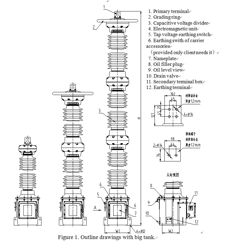
三、Dimensions of the Voltage Transformers
|
Voltage range(kV) |
No. of capacitor |
Grading ring or not |
H mm |
W1×W2 mm×mm |
D mm |
|
35 |
1 |
× |
1535~1770 |
470×324 |
22 |
|
66 |
1 |
× |
1535~1770 |
||
|
110 |
1 |
× |
1835~2070 |
||
|
132 |
1 |
× |
2035~2270 |
||
|
150 |
1 |
× |
2245~2470 |
||
|
220 |
2 |
× |
3095~3425 |
||
|
330 |
2 |
√ |
3915~4225 |
||
|
500 |
3 |
√ |
5580~6405 |
Notes:
1)There may be any change of the dimensions for the current transformers because of renewing, the clients must basis on the updated drawings.
2)If the product installation dimensions do not meet the requirements, we can provide transitional mounting bracket to meet the installation requirements.
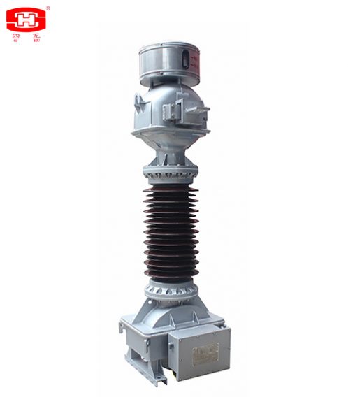
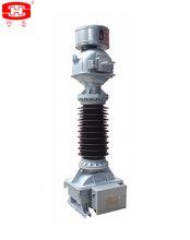
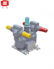
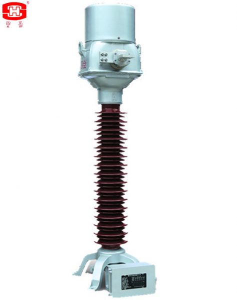
JLD-72.5 type voltage transformers are oil immersed combined current voltage transformer.
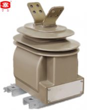
JLD-72.5 type voltage transformers are oil immersed combined current voltage transformer. The part of VT is imitation shape tank structure. The core was used cold-rolled silicon steel strip to folded. The high voltage coil adopts sectional winding method. The part of CT is inverted structure. The primary conductor passes through the center of the secondary winding and has high measurement accuracy. The secondary windings are protected within the aluminum shield. The rods part of the two body are insulated with capacitive screen structure. They are inside the porcelain bushing and reduce the amount of oil used in the transformer. We select corrugated metal expander as oil temperature variation compensator and can inspect the oil level through window. Outline dimensions drawing and structure shown in Figure 1.
一、Service condition
a. outdoor
b. Surrounding Temperature Max. temperature: 40℃, min. temperature :-45℃.
c. Altitude will not exceed 1000m.
d. Relative Humidity Max. 95%/ Min. 35%
e. 24h average ambient temperature shall not exceed 35℃.
f. Solar radiation level reaching 1000W/m2 (sunshine at noon) shall be considered.
g. Pollution Level of the area can be Ⅳ. The ambient air is polluted by dust, smoke, corrosive gas, corrosive steam and salt.
h. Wind pressure shall not exceed 0.7kPa (equal to wind speed 34m/s).
二、Main Technical Parameters
|
Main Technical Parameters |
|||||||
|
Type |
JLD-72.5 |
Rated frequency |
60Hz |
||||
|
Highest voltage |
72.5kV |
Insulation level |
140/350kV |
||||
|
CT Ith.1s |
31.5kA |
CT Idyn. |
80kA |
||||
|
Rated voltage factor |
1.2 con./1.5 30s |
Limited burden |
500VA |
||||
|
Instalation |
outdoor |
Creepage distance |
2248mm |
||||
|
CT. |
|||||||
|
secondary terminal |
current rated |
accuracy class |
burden |
||||
|
1S1-1S5 |
2S1-2S5 |
1200/5A |
5P20 |
50VA |
|||
|
1S2-1S5 |
2S2-2S5 |
1000/5A |
|||||
|
1S3-1S5 |
2S3-2S5 |
900/5A |
|||||
|
1S1-1S4 |
2S1-2S4 |
800/5A |
|||||
|
1S2-1S4 |
2S2-2S4 |
600/5A |
|||||
|
1S3-1S4 |
2S3-2S4 |
500/5A |
|||||
|
1S4-1S5 |
2S4-2S5 |
400/5A |
|||||
|
1S1-1S3 |
2S1-2S3 |
300/5A |
|||||
|
3S1-3S3 |
200/5A |
0.2 |
50VA |
||||
|
3S1-3S2 |
100/5A |
||||||
|
VT. |
|||||||
|
secondary terminal |
primary voltage |
secondary voltage |
accuracy class |
burden |
|||
|
X1-X2 |
42000V |
120V |
0.2 |
75VA |
|||
|
Y1-Y2 |
42000V |
120V |
3P |
75VA |
|||
三、Outline Dimensions and Structure Drawing
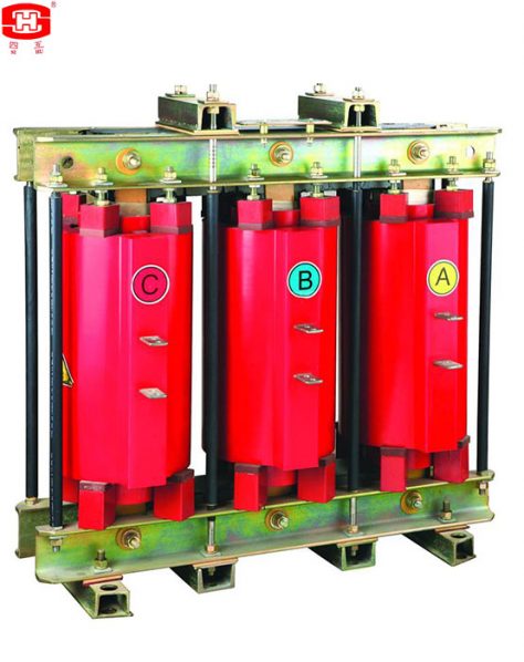
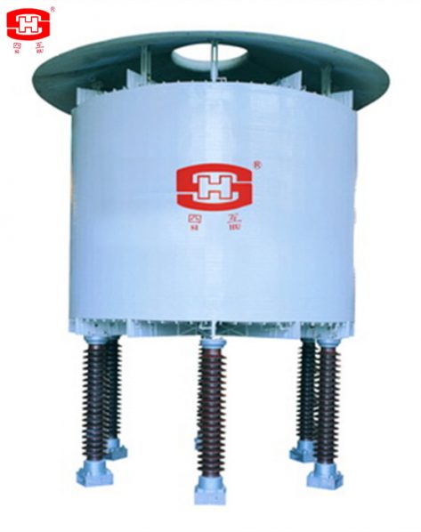
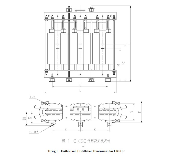
CKSC Series Reactors
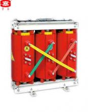
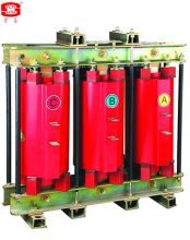
CKSC series reactor is suitable for a power system of 6~10kV. It is connected seriesly with high voltage parallel capacitor group to depress a wave deformation in the system.
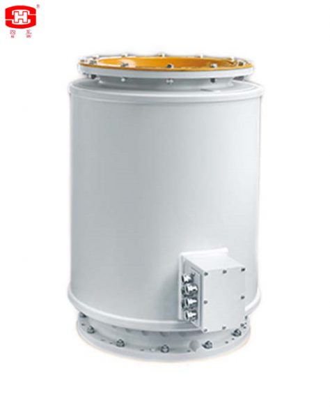
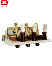
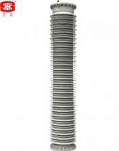
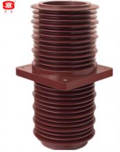
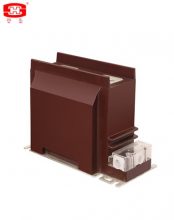
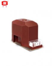
The current transformers match 35~1000kV high voltage switchgears are including the current transformers for outdoor of busbar going through with the stainless steel or aluminium cases, secondary windings with the insulating material wound, casted by epoxy resin with the flanges, installed with the enclosures and so on. The shapes, dimensions, technical parameters and service environments can be designed according to the requirements of the clients.
The current transformers match 35~1000kV high voltage switchgears are including the current transformers for outdoor of busbar going through with the stainless steel or aluminium cases, secondary windings with the insulating material wound, casted by epoxy resin with the flanges, installed with the enclosures and so on. The shapes, dimensions, technical parameters and service environments can be designed according to the requirements of the clients.
一、Profile of products
The current transformers match 35~1000kV high voltage switchgears are including the current transformers for outdoor of busbar going through with the stainless steel or aluminium cases, secondary windings with the insulating material wound, casted by epoxy resin with the flanges, installed with the enclosures and so on. The shapes, dimensions, technical parameters and service environments can be designed according to the requirements of the clients.
Surface: There are different kinds of the current transformers for GIS according to the requirements of the clients, the the surface of the current transformers which used in SF6 gas are wound by insulating tap, casted by epoxy resin or casted with the flanges by epoxy resin; the the surface of the current transformers which used in air are casted by indoor or outdoor epoxy resin, printing after casted by epoxy resin, or closed by the metal enclosures.
The current transformers which used in SF6 gas are manufactured in the constant temperature, humidity and clean room, then dry and vacuum, the moisture contained is very low, they can be used inside the pressure vessel of GIS directly without dry by the clients; they are very clear and can match the cleaning requirement of the GIS.
There is good aging resistivity for the current transformers which casted by indoor or outdoor epoxy resin or printing after casted by epoxy resin used in the air.
There is good agglutinate strength of metal and secondary windings which joined by epoxy resin for the current transformers which closed by the metal enclosures, the protection degree can reach IP66, and there is the function of preventing condensation for the secondary termanils box.
Protection of products: The current transformers which used in SF6 gas should be packed by vacuum to prevent moisture, and be cushioned to prevent damnify during transportation.
The current transformers which used in the air should be packed by the plasic film to prevent moisture, and be cushioned to prevent damnify during transportation.
二、Technical parameters
The other technical parameters please see table 1.
|
Rated Frequency (Hz) |
Rated Primary Current (A) |
Rated Secondary Current (A) |
Accuracy Classes Combination |
Instrument Security Factor |
Rated Output cosΦ= 0.8 (VA) |
Rated Voltage (kV) |
|
50 60 |
50~4000 |
5 1 |
0.2S 0.2 0.5S 0.5 5P5~5P70 10P5~10P70 PX PR TPS TPX TPY TPZ |
≤5 ≤10 ≤15 ≤20 ≤25 |
5~60 |
0.66 |
Note: These are the routine parameters in the above table, if there is any different parameters required, we can design according to the technical parameters of the clients.
三、Service conditions
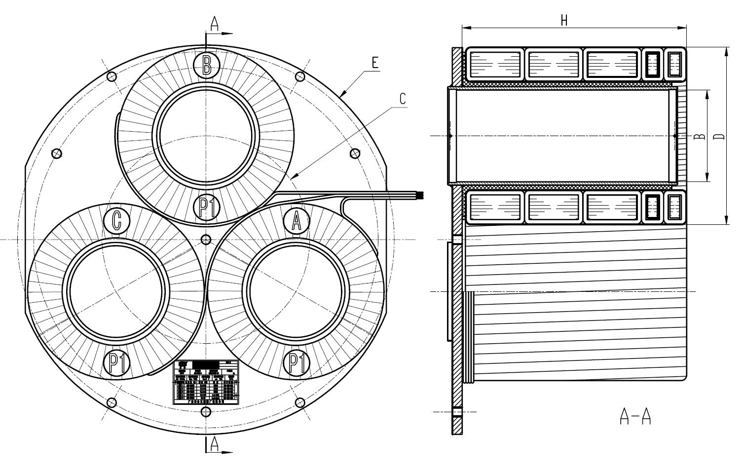
Drawing 1 CTs for GIS (casted with the flanges) outline and installation dimensions
Table 1 Dimensions of drawing 1
|
Symbols of drawing 1 |
Dimension of each product type (mm) |
|||||||
|
66kV |
110~150kV |
220kV |
||||||
|
B |
Φ115 |
Φ140 |
Φ220 |
|||||
|
C |
Φ285 4 |
Φ316.4 4 |
Φ550 4 |
|||||
|
D |
Φ255 |
Φ273 |
Φ478 |
|||||
|
E |
Φ552 |
Φ593.5 |
Φ1060 |
|||||
|
H |
280 |
380 |
144 |
344 |
445 |
325 |
460 |
585 |
Note: These are the routine dimensions in the above table, if there is any different dimensions required, we can design according to the the clients.
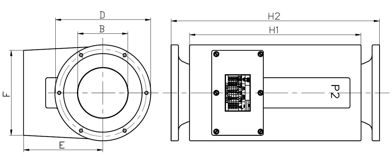
Drawing 2 CTs for GIS (casted by epoxy resin with flanges) outline and installation dimensions
Table 2 Dimensions of drawing 2
|
Symbols of drawing 2 |
Dimension of each product type (mm) |
|||||||
|
66kV |
110kV |
220kV |
330kV |
|||||
|
B |
Φ115 |
Φ136 |
Φ220 |
Φ255 |
||||
|
D |
Φ242 |
Φ260 |
Φ478 |
Φ532 |
||||
|
E |
202 |
215 |
380 |
410 |
||||
|
F |
210 |
230 |
305 |
325 |
||||
|
H1 |
402 |
565 |
465 |
953 |
665 |
1025 |
725 |
1085 |
|
H2 |
510 |
673 |
565 |
1053 |
825 |
1185 |
885 |
1245 |
Note: These are the routine dimensions in the above table, if there is any different dimensions required, we can design according to the the clients.
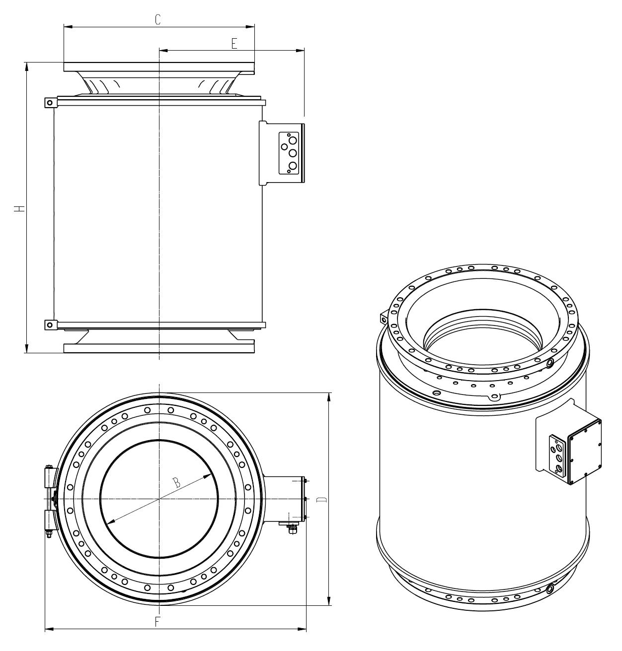
Drawing 3 CTs for GIS (closed by the metal enclosures) outline and installation dimensions
Table 3 Dimensions of drawing 3
|
Symbols of drawing 3 |
Dimension of each product type (mm) |
||||||||
|
500kV |
750kV |
1000kV |
|||||||
|
B |
Φ415 |
Φ670 |
Φ870 |
||||||
|
C |
Φ680 |
Φ840 |
Φ1080 |
||||||
|
D |
Φ770 |
Φ1160 |
Φ1390 |
||||||
|
E |
519 |
705 |
830 |
||||||
|
F |
940 |
1290 |
1530 |
||||||
|
H |
520 |
780 |
1040 |
650 |
900 |
1150 |
755 |
1005 |
1255 |
Note: These are the routine dimensions in the above table, if there is any different dimensions required, we can design according to the the clients.
The combined transformers combinate the characters of inductive voltage transformer and inductive current transformer
The combined transformers combinate the characters of inductive voltage transformer and inductive current transformer, and it also has the function of current transformer and voltage transformer. The insulation material is SF6 gas. The bushing of the instrument transformer is made by silicon rubber or porcelain
The combined instrument transformer shall be suitable for measurement control and relay protection in the outdoor AC power system of nominal voltage 72.5~550kV, and frequency of 50 or 60Hz. Outline and the Installation Dimensions shown in Figure 1.
一、Service Conditions
a. Ambient air temperature: maximum 40℃, minimum -40℃, average value of the ambient air temperature does not exceed 30℃ measured during a period of 24h.
b. Altitude: The altitude does not exceed 1000m (this is the routine requirement, if there is any different requirement, we can provide the products with 2000m, 3000m, 4000m or 5000m altitude according to the clients’ requirements)
c. The average value of the relative humidity does not exceed 95% at 25℃ measured during a period of one month
d. The maximum wind speed does not exceed 34m/s
e. Earthquake intensity does not exceed 8 degree
f. There have to be no gas that may seriously affect the insulation and conductive ability of electric equipments, steam, ash, salt, chemical deposit, pollution and corrosive or explosive material.
Table 1
|
Rate voltage( kV) |
72.5 |
126 |
145 |
170 |
252 |
363 |
420 |
550 |
|
power-frequency withstand voltage (r.m.s) (kV) |
140 |
230 |
275 |
325 |
460 |
510 |
630 |
680 |
|
Rated lightning impulse withstand voltage (peak) (kV) |
325 |
550 |
650 |
750 |
1050 |
1175 |
1425 |
1550 |
|
Rated switching impulse withstand voltage (peak) (kV) |
–
|
–
|
– |
–
|
–
|
950 |
1050 |
1175 |
|
Rated frequency( Hz) |
50/60 |
|||||||
|
Creepage distance mm/kV |
25~31 or more |
|||||||
|
Insulation level |
E |
|||||||
|
Ambient air temperature |
-30/+50℃ (special design is available of -60℃) |
|||||||
|
Current transformer part |
||||||||
|
Rated current( A) |
100A ~ 4000A |
|||||||
|
Rated secondary current (A) |
1A, 5A or others |
|||||||
|
Accuracy class |
0.2S、0.5S、5P、10P、PX、PR、TPX、TPY、TPZ or others |
|||||||
|
Voltage transformer part |
||||||||
|
Rated primary voltage (kV) |
66/v√3、110/√3、132/√3、150/√3、220√3、330/√3、380√3 or 500/√3 |
|||||||
|
Rated secondary voltage |
100/√3、100 or others |
|||||||
|
Rated Voltage factor |
1.5/30s,1.9/8h or others |
|||||||
|
Accuracy class |
0.2、0.5、3P、6P or others |
|||||||
Standard: GB 20840.1、GB 20840.2、GB 20840.3 IEC 61869-1、IEC 61869-2、IEC 61869-3、ANSI C57.13
Table 2 Unit:mm
|
Rate voltage (kV) |
H1 |
H2 |
A |
B |
C |
D |
|
72.5 |
2450 |
600 |
780 |
540 |
400 |
20 |
|
126 |
2862 |
960 |
877 |
600 |
450 |
24 |
|
145 |
3112 |
1150 |
950 |
620 |
450 |
24 |
|
170 |
3412 |
1255 |
950 |
620 |
450 |
24 |
|
252 |
4025 |
2105 |
1105 |
800 |
560 |
24 |
|
363 |
4434 |
2950 |
1200 |
860 |
560 |
24 |
|
420 |
5324 |
3350 |
1200 |
860 |
600 |
24 |
|
550 |
6210 |
4380 |
1450 |
980 |
900 |
28
|
三、Outline and the Installation Dimensions
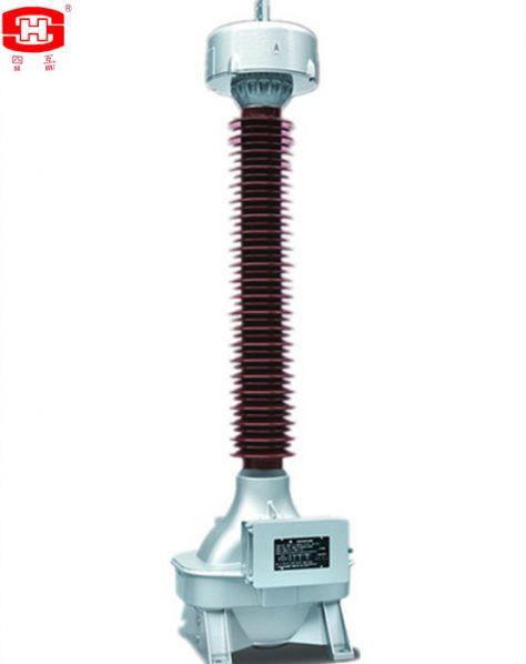
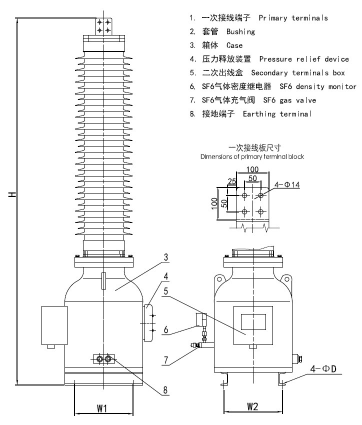
The inductive voltage transformers which the insulation material is SF6 gas. The bushing of the voltage transformer is made by silicon rubber or porcelain.
The inductive voltage transformers which the insulation material is SF6 gas. The bushing of the voltage transformer is made by silicon rubber or porcelain. There are some aluminium electrodes inside the voltage transformer, to improve the electric field distribution inside the voltage transformer. There is a pressure relief device at the top of the voltage transformer, when the pressure is more than 0.8MPa (1.0 MPa only for 500 kV) if the voltage transformer is discharge inside, the relief device will be broken to release the pressure and send an alarm information. There is a SF6 density monitor fix at the base, it can indicate the SF6 pressure which inside the voltage transformer (its indicated value is the SF6 pressure at 20℃), and it will provide an information when the SF6 pressure is drop down to the minimum service pressure of the current transformer, to remind the user replenish the SF6 gas to the rated pressure. The secondary terminals block is casted by epoxy resin, the frame of the secondary terminals box is a seal structure, it suits for outdoor.
一、Service Conditions :
二、Technical Parameters:
三、Rated output and relative accuracy class (cosφ=0.8 lag) please see table 1
Table 1
|
Winding |
Measuring Winding |
Protective Winding |
Residual Voltage Winding |
Winding |
Measuring Winding |
Protective Winding |
|
Terminals Marking Accuracy Class |
1a-1n |
2a-2n |
3a-3n |
Terminals Marking |
1a-1n |
2a-2n |
|
0.2 |
0.5 |
0.5 |
Accuracy Class |
0.2 |
0.5 |
|
|
Rated Output (VA) |
100 |
– |
– |
Rated Output (VA) |
100 |
– |
|
– |
150 |
– |
– |
150 |
||
|
Winding |
75 |
– |
100 |
75 |
– |
|
|
Measuring Winding |
Protective Winding |
Residual Voltage Winding |
Winding |
Measuring Winding |
Protective Winding |
|
|
Terminals Marking Accuracy Class |
1a-1n |
2a-2n |
3a-3n |
Terminals Marking |
1a-1n |
2a-2n |
|
0.2 |
0.5 |
0.5 |
Accuracy Class |
0.2 |
0.5 |
|
|
Rated Output (VA) |
100 |
– |
– |
Rated Output (VA) |
100 |
– |
|
– |
150 |
– |
– |
150 |
||
|
Winding |
75 |
– |
100 |
75 |
– |
|
|
Measuring Winding |
Protective Winding |
Residual Voltage Winding |
Winding |
Measuring Winding |
Protective Winding |
Note: Each thermal limit burden for protective winding is 2000VA.
四、Arcing distance and creepage distance of outer insulation please see table 2.
|
Rated voltage(kV) |
Arcing distance(mm) |
Creepage Distance (mm) |
||
|
Pollution Level Ⅱ (W1) |
Pollution Level Ⅲ (W2) |
Pollution Level Ⅳ(W3) |
||
|
35kV |
≥410 |
≥810 |
≥1013 |
≥1256 |
|
66kV |
≥720 |
≥1450 |
≥1813 |
≥2248 |
|
110kV |
≥1010 |
≥2520 |
≥3150 |
≥3906 |
|
132kV |
≥1160 |
≥2900 |
≥3625 |
≥4495 |
|
150kV |
≥1350 |
≥3400 |
≥4250 |
≥5270 |
|
220kV |
≥2010 |
≥5040 |
≥6300 |
≥7812 |
|
330kV |
≥2360 |
≥7260 |
≥9075 |
≥11253 |
|
380kV |
≥3323 |
≥8400 |
≥10500 |
≥13020 |
|
500kV |
≥3980 |
≥11000 |
≥13750 |
≥17050 |
五、Insulation requirements for the primaries please see table 3.
| Rated voltage (kV) | 35 | 66 | 110 | 132 | 150 | 220 | 330 | 380 | 500 | |
| power-frequency withstand voltage (r.m.s) (kV) | 95 | 160 | 230 | 275 | 325 | 460 | 510 | 630 | 740 | |
| The wet test for the current transformer of power-frequency withstand (r.m.s) (kV) | 95 | 160 | 230 | 275 | 325 | 460 | 510 | 630 | 740 | |
| Rated switching impulse withstand voltage (peak) (kV) | / | / | / | / | / | / | 950 | 1050 | 1175 | |
| Rated lightning impulse withstand voltage (peak) (kV) | 200 | 325 | 550 | 650 | 750 | 1050 | 1175 | 1425 | 1550 | |
| chopped ligtning impulse voltage (peak) (kV) | 230 | 343 | 635 | 750 | 865 | 1208 | 1351 | 1640 | 1930 | |
| power-frequency withstand voltage at the SF6 gas pressure 0MPa (kV) | 30 | 54 | 95 | 109 | 128 | 190 | 272 | 315 | 413 | |
| Partial discharge level | prestressing performed voltage (r.m.s) (kV) | 76 | 112 | 184 | 220 | 260 | 368 | 408 | 504 | 592 |
|
Test voltage 1.2Um or Um (kV) PD≤10pC |
49 | 87 | 126 | 145 | 170 | 252 | 363 | 420 | 550 | |
|
Test voltage 1.2Um/√3 (kV) PD≤5pC |
28 | 50 | 87 | 100.5 | 118 | 174 | 252 | 291 | 381 | |
六、Mechanical requirements for the primary terminals please see table 4.
|
Rated voltage (kV) |
35 |
66 |
110 |
132 |
150 |
220 |
330 |
380 |
500 |
|
Mechanical requirements (horizontal of two directions and vertical) (N) |
— |
500 |
1000 |
1000 |
1000 |
1250 |
1250 |
1500 |
1500 |
|
Applied to the primary terminals with duration (s) |
— |
60 |
60 |
60 |
60 |
60 |
60 |
60 |
60 |
七、Dimensions of the voltage transformers
The outline and installation dimensions please see drawing 1, and the dimensions of the primary termanils please see table 5.
|
Rated voltage(kV) |
H(mm) |
W1(mm) |
W2(mm) |
D(MM) |
|
35 |
1050 |
335 |
335 |
16 |
|
66 |
1500 |
400 |
400 |
20 |
|
110 |
1905 |
450 |
450 |
20 |
|
132 |
2150 |
450 |
450 |
20 |
|
150 |
2350 |
450 |
450 |
20 |
|
220 |
3470 |
600 |
600 |
24 |
|
330 |
4150 |
600 |
600 |
24 |
|
380 |
4720 |
680 |
680 |
32 |
|
500 |
5920 |
750 |
750 |
32 |
Drawing 1 JDQXF-□W outline and installation dimensions
Voltage Transformers Match High Voltage Switchgears
The voltage transformers are match 35~1000kV GIS or PASS high voltage switchgears. Their dimensions,
technical parameters and service environments can be designed according to the requirements of the clients.
The enclosures of the voltage transformers are made by metal which is steel or aluminium, there are two kinds
of the technics for the enclosures: casted or welded.
一、Service conditions
Note: If there is any different from the service conditions of the above, we can design according to the requirements of the clients.
二、Main Technical Parameters
三、Voltage ratios, maximum rated outputs and corresponding accuracy classes please see below table.


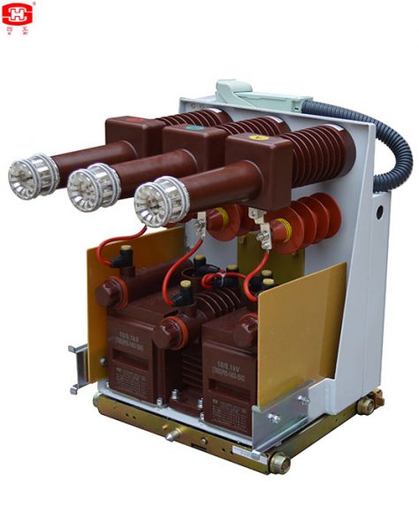
Being a compact structure, with the voltage transformers and arresters in a truck, the trucks are suitable for the switchgears with the widths 650mm or 800mm, and the height 537mm of the trucks can be installed in the under layer of the switchgears.
Being a compact structure, with the voltage transformers and arresters in a truck, the trucks are suitable for the switchgears with the widths 650mm or 800mm, and the height 537mm of the trucks can be installed in the under layer of the switchgears. The trucks have the electromagnetic locks which can prevent disoperation, and with the earthed copper bars in the chassis of trucks. The trucks can equipped the assistant switches S8 and S9, which can provide the structures with 3-open 2-close, 4-open 1-close or 5-open and so on.We can design the trucks according to the customers' special requirements as well.
Table 1 Main Data of VTs for YBCⅢ Trucks
|
Type |
Rated Primary Voltage (kV) |
Rated Secondary Voltage (kV) |
Rated Voltage of Residual Winding (kV) |
Accuracy Class and Burden of Secondary (VA) |
Limiting Output (VA) |
||
|
Cl. 0.2 |
Cl. 0.5 |
Cl. 1 |
|||||
|
JDZX30(G)-10RC |
10/√3 |
0.1/√3 |
0.1/3 |
15 |
30 |
60 |
350 |
|
JDZX18(G)-10RC |
10/√3 |
0.1√3 |
0.1/3 |
20 |
50 |
100 |
500 |
Note: The accuracy classes and burdens of residual windings are 6P, 50VA or 100VA.
Table 2 Main Data of VTs for YBCⅡ Trucks
|
Type |
Rated Primary Voltage (kV) |
Rated Secondary Voltage (kV) |
Accuracy Class and Burden of Secondary (VA) |
Limiting Output (VA) |
||
|
Cl. 0.2 |
Cl. 0.5 |
Cl. 1 |
||||
|
JDZ19(G)-10RJC and JDZ19(G)-10RVJC |
10 |
0.1 |
15 |
30 |
60 |
350 |
|
JDZ21(G)-10R(GB) and JDZ21(G)-10RV(GB) |
10 |
0.1 |
50 |
100 |
200 |
500 |
Table 3 Main Data of Fuses
|
Type |
Rated Voltage (kV) |
Rated Current (A) |
Breaking Ability (kA) |
|
|
XRNP1-3.6 |
3.6 |
0.3,0.5,1,2,3 |
50 |
|
|
XRNP1-7.2 |
7.2 |
|||
|
XRNP1-12 |
12 |
Table 4 Main Data of Arresters
|
Type |
System Rated Voltage (kV) |
Rated Voltage (kV) |
Continuous Operating Voltage (kV) |
Reference Voltage at DC 1mA (kV) |
Max Residual Voltage at Nominal Current (8/20μs 5kA) (kV) |
Max Residual Voltage at Switching Impulse (kV) |
Current Impulse |
|
|
2ms Rectangular Wave (18 times) (A) |
4/10μs Wave (2 times) (kA) |
|||||||
|
YH5WS-17/50 |
10 |
17 |
13.6 |
≥25 |
50 |
42.5 |
100 |
100 |
Note: The data listed in the above table are the normal ones, or we can design them according to the customers’ special requirements.
Outline drawing and installation dimensions
There are two structures for the trucks:
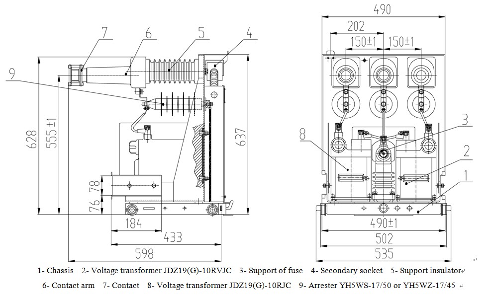
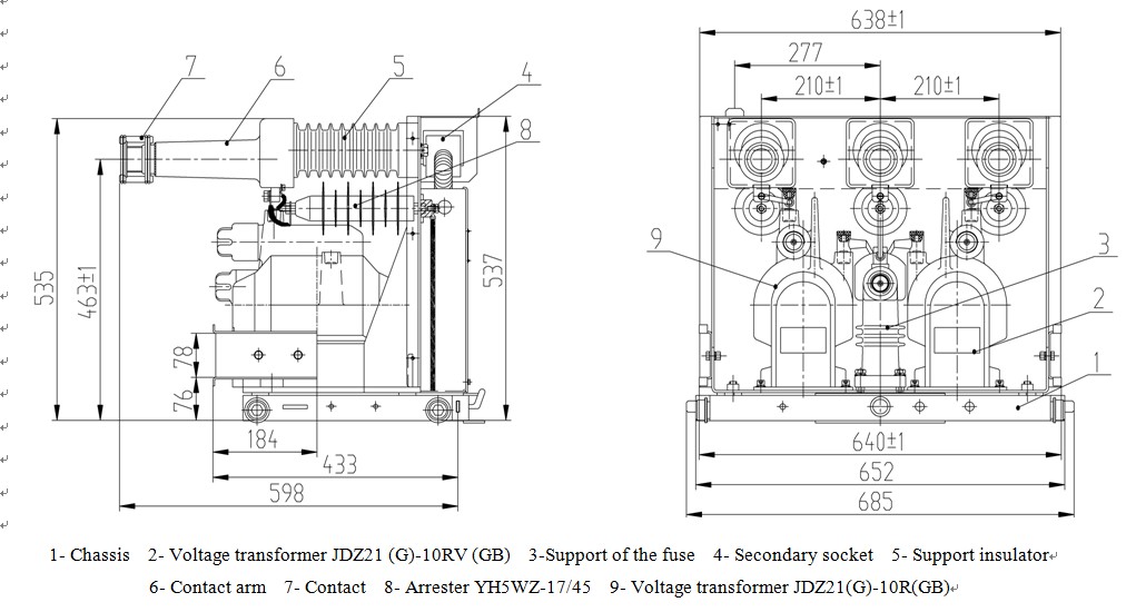
a. 2 VTs structure with type YBCⅡ-12: 2 units voltage transformers with fuses, JDZ19 (G)-10RJC, JDZ19 (G)-10RVJC or JDZ21 (G)-10R (GB), JDZ21 (G)-10RV (GB) in V-connection, and with a fuse support.
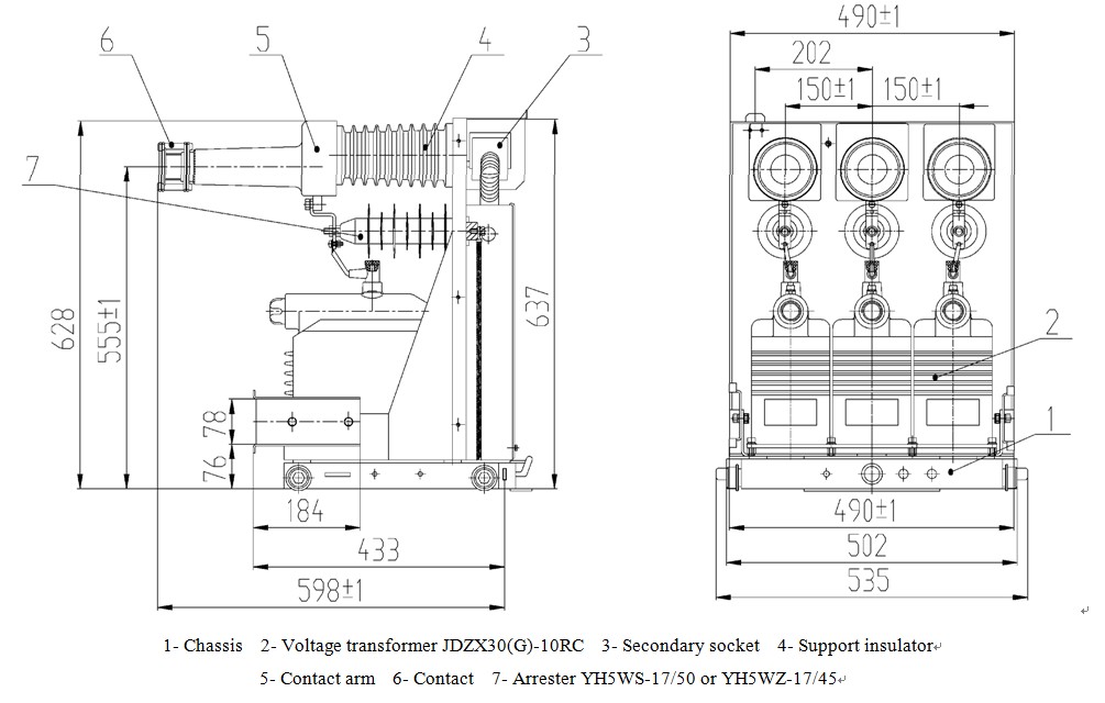
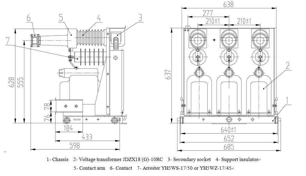
b. 3 VTs structure with type YBCⅢ-12: 3 units voltage transformers with fuses, JDZX30 (G)-10RC or JDZX18 (G)-10RC in Y-connection, and their residual voltage windings are for symmetrical monitor on 3-phase voltage.
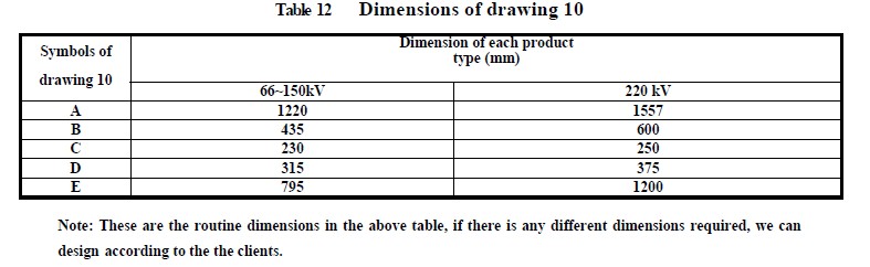
Drawing 1. Outline and Installation Dimensions for Type YBCⅡ-12/150-650
Drawing 2 Outline and Installation Dimensions for Type YBCⅢ-12/150-650
Drawing 3 Outline and Installation Dimensions for Type YBCⅡ-12/210-800
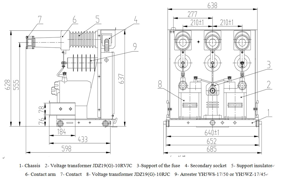
Drawing 4 Outline and Installation Dimensions for Type YBCⅢ-12/210-800
Drawing 5 Outline and Installation Dimensions for Type YBCII-12/150-650

Drawing 6 Outline and Installation Dimensions for Type YBCII-12/210-800
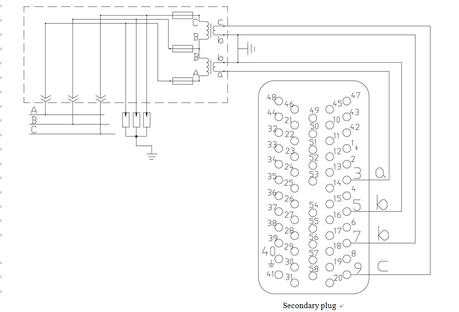
Drawing 7 Electric Connection for Type YBC II-12
Drawing 8 Electric Connection of Two 3-open-2-close Assistant Switches S8 or S9 for Type YBC II-12

Drawing 9 Eearthing Connection for Type YBC III-12 Drawing 10 Electric Connection of Type YBC III-12
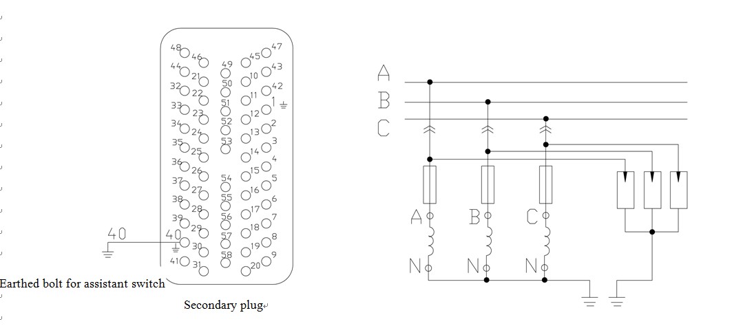
Drawing 11 Inner Secondary Connection for Type YBC III-12
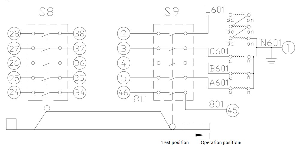
Note: All the numbers lead to the secondary socket; 2.5mm2 strand wire shall be used for secondary circuit of voltage transformers (colors are according to the phase sequence).
Search Results for :